Honeywell L4097B and LS8097A Leak-Safe Limit Control User Guide


L4097B and LS8097A LEAK-SAFE
LIMIT CONTROL
This is a legacy product document supported by Resideo. This product is no longer manufactured.
APPLICATION
The L4097B and LS8097A are panel-mounted immersion type temperature controls that provide high limit protection for domestic hot water heaters and hydronic heating equipment. The L4097B may be used for warm air applications. On a temperature rise to the non-adjustable cutout point, a spot switch in the control breaks, shutting down the burner. The switch must be manually reset.
The leak-safe feature of these controls provides maximum safety in case of capillary failure. If a leak develops in the capillary, the effective setpoint decreases as fill is lost. If the capillary breaks, or when substantial fill is lost, the switch will open, cutting off power to the burner.
The L4097B, which controIs line voltage circuits, is available in cutout settings of 95 C [203 F], 110 C [230 F] and 145 C [293 F]. The LS8097A, which controls self-powered gas circuits, has a cutout setting of 110 C [230 F]. Other cutout settings are available on request. The L4097B can have a coiled or straight capillary from 31.7 mm to 3.65 metres [1.25 in. to 12 feet] long.
INSTALLATION
CAUTION
1. Installer must be a trained, experienced serviceman.
2. Disconnect power before beginning installation to prevent electrical shock or equipment damage.
3. Do not make sharp or repeated bends in the capillary. Bends should be no less than 25.4mm [1 inch] radius.
Follow boiler or water heater manufacturer’s instructions, if available; otherwise, follow general instructions below.
LOCATION
The coiled sensing element must be installed in an immersion well in a location where water or average temperature can circulate freely around it. Usually, tapping is provided by the equipment manufacturer at the proper location.
Locate a straight capillary model where it can best sense a change in temperature conditions. Under normal operating conditions, the ambient temperature at the capillary should be 17 C [30 F] below the cutout point.
The switch assembly can be mounted in any convenient location, limited only by the length of the capillary.
ELECTRICAL RATINGS: Do not exceed the following ratings
| L4097B | 24V AC | 24V AC | 120V AC | 240V AC | 277V AC |
| Amps Full Load | 2 | 2 | 10 | 5 | — |
| Amps Locked Rotor | #NAME? | #NAME? | 60 | 30 | — |
| Resistive | #NAME? | #NAME? | 25 | 25 | 25 |
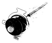

Fig. 1 – Components of the L4097B and LS8097A Leak-safe Limit Control.
The maximum ambient temperature at the switch location is 87 C [190 F].
MOUNT COILED SENSING ELEMENT
The coiled sensing element on this control must be installed in an immersion well (not supplied). Order well assembly No. 45.001.098-001.
- If no tapping is provided, prepare one, properly sized and threaded, at the selected location. Spud threads are 1/2 14 BSP. Tr, EXT.
- Screw immersion well assembly into tapping.
- Fill boiler or water heater and check for leakage. Tighten spud if necessary.
- Insert an element into the well until it bottoms and holds while inserting the clip.
- Push well spud clip into spud next to capillary until capillary is held firmly in well.

Fig. 2 – Installing sensing element in an immersion well.
MOUNT STRAIGHT SENSING ELEMENT
The L4097B can be mounted in any position. The ambient temperature at the switch must not exceed 150 C [300F], but should always be 14 C [25 F] lower than the normal operating temperature.
MOUNT SWITCH ASSEMBLY
The L4097B can be mounted in any position. Fasten with 2 screws.
Carefully coil excess capillary beneath switch assembly, making sure no bend in the capillary is less than 25.4 mm [1 inch] radius.
WIRING
All wiring must comply with local codes and ordinances. Use approved enclosure to cover wiring terminals. See Figs. 3 and 4 for internal schematic and general hookup.

Fig. 3 – L4097B internal schematic and typical connections in line voltage control system.

Fig. 4 – LS8097A internal schematic and typical connections in a self-powered gas control system.
When using the LS8097A in a thermocouple ECO circuit, attention must be given to the wire length to avoid high resistance. See Fig. 5.
| Thermocouple Length–Q309, | Maximum Wire Length (in cm) depending on diameter | |
| (cm) | 2,5 mm² | 4 mm² |
| 30 | 2 x 85 | 2 x 130 |
| 45 | 2 x 65 | 2 x 100 |
| 60 | 2 x 50 | 2 x 80 |
| 75 | 2 x 30 | 2 x 45 |
| 90 | — | 2 x 20 |
| 100 | — | — |
Fig. 5 – Maximum wire length for ECO circuits.
OPERATION
Cutout temperatures of the L4097B and LS8097 are indicated on the mounting flange.
On a water temperature rise to the cutout setting of the 4097B, the spst switch in the control opens, cutting off power to the burner. After the temperature has cooled to the cut-in temperature (cut-out temperature minus differential), the switch can be closed by pushing and releasing the reset button in the front of the switch assembly.
Honeywell Limited, Home and Building Control, North York, ON M2H 3N7
Printed in Canada