Honeywell VR8305 Direct Ignition Dual Automatic Valve Combination Gas Controls User Guide
Honeywell VR8305 Direct Ignition Dual Automatic Valve Combination Gas Controls User Guide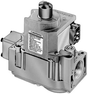

The VR8305 Direct Ignition Dual Automatic Valve Combination Gas Controls are for use with direct ignition systems in gas-fired appliances. The controls include a safety shut-off, a manual valve, two automatic operators, and a pressure regulator.
- Used with S89C,E,F and S87 series 5 and later.
- Used with 24 Vac heating appliances that burn natural or liquefied petroleum (LP) gas.
- Capacity rated up to 300 feet3 /hour at 1 inch wc pressure drop [8.5 meters3 /hour at 0.25 kPa]. Maximum capacity rated up to 415 feet3 /hour [11.8 meters3 /hour]. Minimum capacity rated at 30 feet3 /hour [0.8 meters3 /hour].
- Solenoid operated dual first automatic valves open on thermostat call for heat and close when call for heat ends.
- Opening of the solenoid-operated second automatic valve engages the servo pressure regulator. Loss of power or gas closes the valve.
- Two-position gas control knob has ON and OFF positions.
- All adjustments and wiring connections accessible from top of the control.
- Compact size.
- Straight-through body pattern; right angle adapters available for inlet and outlet.
- Available in 1/2 inch and 3/4 inch inlet and outlet. 1/2 inch and 3/4 inch straight and angle adapters available.Adjustable servo regulator effectively maintains almost constant gas output pressure under wide fluctuations in gas supply pressure.
- Inlet screen included.
- Wiring terminal block color-coded brown to indicate direct ignition control.
- May be installed at any angle including vertically between 0 and 90 degrees from the upright position.
- 1/4 inch male quick-connect terminals for electrical connections.
- -40° F to +175° F [-40° C to +79° C] temperature range.
(VR8305H 0° F to 175° F [-18° C to 79° C]). - Inlet and outlet pressure taps included; both taps accessible from top of control.
- Standard, slow, and step-opening models available.
- Natural to LP gas conversion kit included for standard opening and slow-opening models.
- LP to natural gas conversion kit available for standard opening and slow- opening models.
Specifications
IMPORTANT: The specifications given in this publication do not include normal manufacturing tolerances. Therefore a particular unit may not exactly match the listed specifications. Also, this product is tested and calibrated under closely controlled conditions, and some minor differences in performance can be expected if those conditions are changed.
MODELS: VR8305 Dual Automatic Valve Combination
Gas Controls for use in Direct Ignition Systems. See
Table 1 for model specifications.
SUPPLY VOLTAGE: 24 Vac, 60 Hz.
CURRENT DRAW: 0.7A.
ELECTRICAL CONNECTIONS: 1/4 inch male quick-connects. Two convenience terminals on top of control (optional). Terminal block color-coded brown. TYPE OF GAS: VR8305 setup for natural gas includes a
393691 LP Conversion Kit. Kit for conversion from LP tonatural gas is available for standard-opening and slowopening models. See Accessories.
TABLE 1—MODEL SPECIFICATIONS.
| Model No. Suffix Letter |
Opening Charac- teristic |
Type of Gas |
Standard Factory Regulator
Settings |
Ranges of Optional Factory Regulator Settings | Ranges of Field Adjustment | |||
| in. wc | kPa | in. wc | kPa | in. wc | kPa | |||
| M | Standard- opening | Natural | 3.5 | 0.9 | 3 to 5 | 0.7 to 1.2 | 3 to 5 | 0.7 to 1.2 |
| LP | 10.0 | 2.5 | 8 to 12 | 2 to 3 | 8 to 12 | 2 to 3 | ||
| P | Step-opening | Natural | Step—0.7, 0.9, 1.2 or 1.7, as ordereda Full Rate— 3.5 |
Step—0.17, 0.22, 0.30 or 0.48, as ordereda Full Rate— 0.9 |
Step—0.7, 0.9, 1.2 or 1.7, as ordereda Full Rate— 3 to 5 |
Step—0.17 0.22, 0.30 or 0.48, as ordereda Full Rate— 0.7 to 1.2 |
Step—none; Full Rate— 3-5 | Step—none; Full Rate— 0.7 to 1.2 |
| LP | Step—1.4, 2.5, 4.0 or 5.5, as ordereda Full Rate— 10 |
Step—0.35, 0.62, 0.99 or 1.37, as ordereda Full Rate— 2.5 |
Step—1.4, 2.5, 4.0 or 5.5, as ordereda Full Rate— 8 to 12 |
Step—0.35, 0.62, 0.99 or 1.37, as ordereda Full Rate— 2-3 |
Step—none; Full Rate— 8-12 | Step—none; Full Rate— 2 to 3 | ||
| H | Slow-opening | Natural | 3.5 | 0.9 | 3 to 5 | 0.7 to 1.2 | 3 to 5 | 0.7 to 1.2 |
| LP | 10.0 | 2.5 | 8 to 12 | 2 to 3 | 8 to 12 | 2 to 3 | ||
Ordering Information
When purchasing replacement and modernization products from your TRADELINE® wholesaler or your distributor, refer to the TRADELINE Catalog or price sheets for complete ordering number, or specify—
- Order number.
- Natural or LP gas.
- Step pressure on VR8305P.
- Accessories, if desired.
- Order separately; transformer, igniter, sensor, module, limit controller, and thermostat or controller as required.
If you have additional questions, need further information, or would like to comment on our products or services, please write or phone:
- 1. Your local Honeywell Residential and Building Controls Division Sales Office (check white pages of your phone directory).
- Residential and Building Controls Division Customer Satisfaction Honeywell Inc., 1885 Douglas Drive North Minneapolis, Minnesota 55422-4386
(In Canada—Honeywell Limited/Honeywell Limitee, 740 Ellesmere Road, Scarborough, Ontario M1P 2V9) International Sales Offices in all principal cities of the world. Manufacturing in Australia, Canada, Finland, France, Germany, Japan, Mexico, Netherlands, Spain, Taiwan, United Kingdom, U.S.A.
CAPACITY
| Size (Inlet x Outlet) |
Capacity
at 1 inch wc
Pressure Dropa |
Minimum
Regulated Capacity |
Maximum
Regulated Capacity |
| 1/2 X 1/2 | 240 feet3/hour [6.8 meter3/hour] |
30 feet3/hour [0.8 meter3/hour] |
340 feet3/hour [9.6 meter3/hour] |
| 1/2 X 3/4 | 270 feet3/hour [7.6 meter3/hour] |
30 feet3/hour [0.8 meter3/hour] |
370 feet3/hour [10.5 meter3/hour] |
| 3/4 X 3/4 | 300 feet3/hour [8.5 meter3/hour] |
30 feet3/hour [0.8 meter3/hour] |
415 feet3/hour [11.8 meter3/hour] |
Capacity based on 1000 btu/feet3, 0.64 specific gravity natural gas at 1 inch wc pressure drop [37.3 MJ/meter3, 0.64 specific gravity natural gas at 0.25 kPa pressure drop].
Use conversion factors in Table 2 to convert capacities for other gasses.
TABLE 2—GAS CAPACITY CONVERSION FACTORS.
| Gas |
Specific Gravity | Multiply
Listed Capacity by |
| Manufactured | 0.60 | 0.516 |
| Mixed | 0.70 | 0.765 |
| Propane | 1.53 | 1.62 |
BODY PATTERN: Straight-through body pattern. INLET X OUTLET SIZES AVAILABLE: 1/2 x 1/2 inch, 1/2 x 3/4 inch, and 3/4 x 3/4 inch. ADAPTERS: Adapters available for 1/2 and 3/4 inch straight and angle connections. Refer to Table 3.
TABLE 3—ADAPTER (FLANGE) PART NUMBERS.
| Inlet/ Outlet Pipe Size |
Flange Type |
Part Number | |
| Without Hex Wrench | With Hex Wrench | ||
| 1/2 inch NPT | Straight | 393690-6 | 393690-16 |
| Elbow | 393690-3 | 393690-13 | |
| 3/4 inch NPT | Straight | 393690-4 | 393690-14 |
| Elbow | 393690-5 | 393690-15 | |
NOTE: Flange Kits include one flange with attached O-ring and four mounting screws.
PRESSURE TAPPING: Inlet and outlet taps standard. Taps accessible from top of gas control. Tap is 1/8 inch NPT with plug containing recess for 3/16 inch Allen wrench.
PRESSURE RATING: A.G.A. rating 1/2 psi [3.5 kPa] inlet pressure.
PRESSURE REGULATION: See Table 1. Regulator adjustment accessible from top of gas control.
MOUNTING: Can be mounted 0 to 90 degrees in any direction, including vertically, from the upright position of the gas control knob.
TEMPERATURE RATING:
VR8305M,P:-40° F to +175° F [-40° C to +79° C].
VR8305H: 0° F to 175° F [-18° C to +79° C].
DIMENSIONS: See Fig. 1.
APPROVALS
American Gas Association design certificate: UP-70-69A.
Canadian Gas Association design certificate: UP-70-69A.
Australian Gas Association certified: 4717. DELTA C: UP-70-69A.
ACCESSORIES
- Flanges, see Table 3.
- 394349 9/64 inch hex tool for flange assembly screws.
- 393691 Natural to LP Gas Conversion Kit.
- 394588 LP to Natural Gas Conversion Kit.
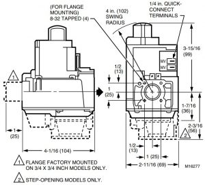
Fig. 1—VR8305 installation dimensions in inches and [millimeters].

Installation
WHEN INSTALLING THIS PRODUCT…
- Read these instructions carefully. Failure to follow them could damage the product or cause a hazardous condition.
- Check the ratings given in the instructions and on the product to ensure the product is suitable for your application.
- Ensure installer is a trained, experienced service technician.
- After installation is complete, use these instructions to check out product operation.
WARNING
FIRE OR EXPLOSION HAZARD CAN CAUSE PROPERTY DAMAGE, SEVERE INJURY, OR DEATH
Follow these warnings exactly:
- Disconnect power supply before wiring to prevent electrical shock or equipment damage.
- To avoid dangerous accumulation of fuel gas, turn off gas supply at the appliance service valve before starting installation, and perform Gas Leak Test after completion of installation.
- Always install sediment trap in gas supply line to prevent contamination of gas control.
- Do not force the gas control knob. Use only your hand to turn the gas control knob. Never use any tools. If the gas control knob will not operate by hand, the gas control should be replaced by a qualified service technician. Force or attempted repair may result in fire or explosion.
CAUTION
Never apply a jumper across or short the valve coil terminals. This could burn out the heat anticipator in the thermostat or damage the electronic direct ignition (DI) module.
IMPORTANT:These gas controls are shipped with protective seals over inlet and outlet tapping. Do not remove seals until ready to connect piping.
Follow the appliance manufacturer’s instructions if available; otherwise, use the instructions provided below.
CONVERTING BETWEEN NATURAL AND LP GAS
WARNING
FIRE OR EXPLOSION HAZARD CAN CAUSE PROPERTY DAMAGE, SEVERE INJURY, OR DEATH
- Do not use a gas control set for natural gas on LP gas or a gas control set for LP gas on natural gas.
- When making conversion, main and pilot burner orifices MUST be changed to meet appliance manufacturer specifications.
Standard-opening or slow-opening gas controls are converted from one gas to another with a conversion kit. To convert from natural gas to LP, use the 393691 LP Conversion Kit that is included with the VR8305 Gas Control. To convert from LP to natural gas, use the 394588 Natural Gas Conversion Kit (order separately). Step-opening gas controls cannot be converted.
To convert control from one gas to another:
- Turn off main gas supply to the appliance.
- Remove the regulator cap screw and pressure regulator adjusting screw. See Fig. 2.
Fig. 2—Top view of gas control. - Remove the existing spring.
- Insert the replacement spring with tapered end down. See Fig. 3.
Fig. 3—Installation of conversion kit in regulated gas control. - Install the new plastic pressure regulator adjustment screw so that the top of the screw is flush (level) with the top of the regulator. Turn the pressure regulator adjustment screw clockwise
- Check the regulator setting either with a manometer or by clocking the gas meter. Refer to Start-Up and Checkout on page 8.
- Install the new cap screw.
- Mount conversion label on control.
- Install control and appliance according to appliance manufacturer’s instructions..


INSTALL ADAPTERS TO GAS CONTROL
Install adapters to gas control as follows:
Flanges
- Choose the appropriate flange for your application.
- Remove seal over gas control inlet or outlet.
- Ensure the O-ring is fitted in the groove of flange. If the O-ring is not attached or is missing, do not use flange.
- With O-ring facing gas control, align the screw holes on the control with the holes in the flange. Insert and tighten the screws provided with the flange. See Fig. 4. Tighten the screws to 25 inch pounds of torque to provide a gas-tight seal.
Fig. 4—Install flange to gas control.

Bushings
- Remove seal over gas control inlet or outlet.
- Apply moderate amount of good quality pipe compound to bushing, leaving two end threads bare. On LP installation, use compound resistant to LP gas. Do NOT use Teflon tape.
- Insert bushing in gas control and carefully thread pipe into bushing until tight.
USING ADAPTERS TO SOLVE SWING RADIUS PROBLEMS
In some field service applications, it is difficult or impossible to thread the control onto the gas supply pipe because of space limitations. This problem can be resolved for most installations by using an adapter. The adapter is installed on the end of the supply pipe in place of the gas control, following the same precautions and instructions that are used for installing the gas control. After the adapter is installed, the gas control is attached to the adapter as outlined above. Note that using an adapter increases the overall length of the gas control.
CHOOSE GAS CONTROL LOCATION
Do not locate the gas control where it can be affected by steam cleaning, high humidity, dripping water, corrosive chemicals, dust or grease accumulation, or excessive heat. To ensure proper operation, follow these guidelines:
- Locate gas control in a well ventilated area.
- Mount gas control high enough above the cabinet bottom to avoid exposure to flooding or splashing water.
- Ensure the ambient temperature does not exceed the ambient temperature ratings for each component.
- Cover gas control if appliance is cleaned with water, steam, or chemicals or to avoid dust and grease accumulation.
- Avoid locating gas control where exposure is possible to corrosive chemical fumes or dripping water.
Locate the gas control in the appliance vestibule on the gas manifold. In replacement applications, locate the gas control in the same location as the old gas control.
Install Pip ing to Gas Control
All piping must comply with local codes and ordinances or with the National Fuel Gas Code (ANSI Z223.1 NFPA No. 54), whichever applies. Tubing installation must comply with approved standards and practices.
- Use new, properly reamed pipe free from chips. If tubing is used, ensure the ends are square, deburred and clean. All tubing bends must be smooth and without deformation.
- Run pipe or tubing to the gas control. If tubing is used, obtain a tube-to-tube coupling to connect the tubing to the gas control.
- Install sediment trap in the supply line to the gas control. See Fig. 5.
Fig. 5—Install sediment trap.

Install Gas Control
TABLE 4—NPT PIPE THREAD LENGTH IN INCHES.
|
Pipe Size |
Thread Pipe This Amount |
Maximum Depth Pipe Can Be Inserted Into
Control |
| 3/8 | 9/16 | 3/8 |
| 1/2 | 3/4 | 1/2 |
| 3/4 | 13/16 | 3/4 |
- This gas control can be mounted 0-90 degrees, in any direction including vertically, from the upright position of the gas control knob.
- Mount the gas control so gas flow is in the direction of the arrow on the bottom of the control.
- Thread pipe the amount shown in Table 4 for insertion into the gas control. DO NOT THREAD PIPE TOO FAR. Valve distortion or malfunction may result if the pipe is inserted too deeply into the gas control.
- Apply a moderate amount of good quality pipe compound (do not use Teflon tape) to pipe only, leaving two end threads bare. On LP installations, use compound resistant to LP gas. Refer to Fig. 6.
- Remove seals over gas control inlet and outlet if necessary.
- Connect pipe to gas control inlet and outlet. Use wrench on the square ends of the gas control. If an adapter is used, place wrench on adapter rather than gas control. Refer to Figs. 2 and 7.
Fig. 7—Proper use of wrench on gas control with and without flanges
WHEN FLANGE IS NOT USED
WHEN FLANGE IS USED


WIRING
- Follow the wiring instructions furnished by the appliance manufacturer, if available, or use the general instructions provided below. All wiring must comply with applicable electrical codes
and ordinances. Disconnect power supply before making wiring connections to prevent electrical shock or equipment damage. - Check the power supply rating on the valve and ensure it matches the available supply. Install transformer, thermostat, and other controls as required.
- Connect control circuit to gas control terminals. See Figs. 2, 8 and 9.
- Adjust thermostat heat anticipator to 0.70 rating stamped on valve operator.
Fig. 8—VR8305 Wiring Connections in S87 Direct Ignition System.

- POWER SUPPLY. PROVIDE DISCONNECT MEANS AND OVERLOAD
PROTECTION AS REQUIRED. - ALTERNATE LIMIT CONTROLLER LOCATION.
- MAXIMUM IGNITER-SENSOR CABLE LENGTH: 3 ft. [.9 m] OR LESS.
- 3A REPLACEABLE FUSE.
- ALARM TERMINAL PROVIDED ON SOME MODELS.

Start-Up and Checkout
WARNING
FIRE OR EXPLOSION HAZARD CAN CAUSE PROPERTY DAMAGE, SEVERE INJURY, OR DEATH
- Do not force the gas control knob. Use only your hand to turn the gas control knob. Never use any tools.
- If the gas control knob will not operate by hand, the gas control should be replaced by a qualified service technician.
GAS CONTROL KNOB SETTINGS
The gas control knob has two settings:
- OFF prevents main burner gas flow.
- ON permits main burner gas flow. Under control of the thermostat and direct ignition module, gas can flow to the main burner.
NOTE: Controls are shipped with the gas control knob in the ON position.
PERFORM GAS LEAK TEST
WARNING
FIRE OR EXPLOSION HAZARD CAN CAUSE PROPERTY DAMAGE, SEVERE INJURY, OR DEATH
Check for gas leaks with rich soap and water solution any time work is done on a gas control.
GAS LEAK TEST
- Paint all pipe connections upstream of the gas control with a rich soap and water solution. Bubbles indicate a gas leak.
- If a gas leak is detected, tighten the pipe connection.
- Stand clear while lighting main burner to prevent injury caused from hidden gas leaks that could cause flashback in the appliance vestibule. Light the main burner.
- With the main burner in operation, paint all pipe joints (including adapters) and gas control inlet and outlet with rich soap and water solution.
- If another gas leak is detected, tighten adapter screws, joints, and pipe connections.
- Replace the part if gas leak cannot be stopped.
TURN ON SYSTEM
Rotate the gas control knob counterclockwise

TURN ON MAIN BURNER
Follow instructions provided by appliance manufacturer or turn thermostat up to call for heat.
CHECK AND ADJUST GAS INPUT TO MAIN BURNER
CAUTION
- Do not exceed the input rating stamped on the appliance nameplate, or manufacturer’s recommended burner orifice pressure for the size orifice used. Ensure the main burner primary air supply is properly adjusted for complete combustion (refer to the appliance manufacturer’s instructions).
- IF CHECKING GAS INPUT BY CLOCKING THE GAS METER:
- Ensure that the only gas flow through the meter is that of the appliance being tested.
- Ensure that other appliances are turned off and that their pilot burners are extinguished (or deduct their gas consumptions from the meter reading).
- Convert the flow rate to Btuh as described in the Gas Controls Handbook (form 70-2602) and compare to the Btuh input rating on the appliance nameplate.
- IF CHECKING GAS INPUT WITH A MANOMETER (PRESSURE GAUGE):
- Ensure the gas control knob is in the PILOT position before removing the outlet pressure tap plug to connect the manometer.
- Turn the gas control knob back to PILOT when removing the manometer and replacing outlet pressure tap plug.
- Shut off the gas supply at the appliance service valve or, for LP gas, at the gas tank before removing the outlet pressure tap plug and before disconnecting the manometer to replace the outlet pressure tap plug.
- Perform the Gas Leak Test at the inlet pressure tap plug.
Standard-Opening and Slow-Opening Pressure Regulator
- The gas control outlet pressure should match the manifold pressure listed on the appliance nameplate.
- With the main burner operating, check the gas control flow rate using the meter clocking method or check the gas pressure using a manometer connected to the gas control outlet pressure tap. Refer to Fig. 2.
- If necessary, adjust the pressure regulator to match the appliance rating. Refer to Table 5 or 6 for the factory set nominal outlet pressures and adjustment ranges. a.
- Remove the pressure regulator adjustment cap and screw.
- Using a screwdriver, turn the inner adjustment screw clockwise
- Always replace the cap screw and tighten firmly to ensure proper operation.
- If the desired outlet gas pressure or gas flow rate cannot be achieved by adjusting the gas control, check the gas control inlet pressure using a manometer at the inlet pressure tap. If the inlet pressure is in the normal range (refer to Table 5 or 6), replace the gas control. Otherwise, take the necessary steps to provide proper gas pressure to the gas control.


Step-Opening Pressure Regulator
- The gas control outlet pressure should match the manifold pressure listed on the appliance nameplate.
- With main burner operating, check the gas control flow rate using the meter clocking method or check the gas pressure using a manometer connected to the gas control outlet pressure tap. Refer to Fig. 2.
- If necessary, adjust the pressure regulator to match the appliance rating. Refer to Table 5 or 6 for factory set nominal outlet pressures and adjustment ranges.
- Remove the pressure regulator adjustment cap screw.
- Using a screwdriver, turn the inner adjustment screw clockwise to increase or counterclockwise to decrease the main burner gas pressure.
- Always replace the cap screw and tighten firmly toensure proper operation.
- If desired outlet pressure or flow rate cannot be achievedby adjusting the gas control, check the inlet pressure using a manometer at inlet pressure tap or upstream of the gas control. If the inlet pressure is in the normal range (refer to Table 5 or
6), replace the existing gas control. Otherwise, take the necessary steps to provide proper gas pressure to the gas control. - Carefully check main burner light off at the step press sure. Ensure the main burner lights smoothly and without flashback to the orifice and that all ports remain lit. Cycle the main burner several times, allowing at least 30 seconds between cycles for the regulator to resume the step function. Repeat after allowing main burner to cool. Readjust the full rate outlet pressure, if necessary, to improve lightoff characteristics.
CHECK SAFETY SHUTDOWN PERFORMANCE
WARNING
FIRE OR EXPLOSION HAZARD CAN CAUSE PROPERTY DAMAGE, SEVERE INJURY, OR DEATH
Perform the safety shutdown test anytime work is done on a gas system.
NOTE: Read steps 1-7 below before starting and compare to the safety shutdown or safety lockout tests recommended for the direct ignition (DI) module. Where they differ, use the procedure recommended for the module.
- Turn off gas supply.
- Set thermostat or controller above room temperature tocall for heat.
- Watch for ignition spark or for glow at hot surface igniter either immediately or following prepurge. See DI module specifications.
- Time length of igniter operation. See DI module specifications.
- After the module locks out, open gas control and ensure there is no gas flow to main burner.
- Set thermostat below room temperature and wait oneminute.
- Operate system through one complete cycle to ensure all controls operate properly
TABLE 5—PRESSURE REGULATOR SPECIFICATION PRESSURES IN INCHES WC.
| Outlet Pressure | ||||||
|
Model |
Type of Gas |
Nominal Inlet
Pressure Range |
Nominal Factory Setting | Setting Range | ||
| Step | Full Rate | Step | Full Rate | |||
| Standard, Slow-opening |
Natural LP |
5.0 – 7.0 12.0 – 14.0 |
— — |
3.5 10.0 |
— — |
3.0 – 5.0 8.0 – 12.0 |
| Step-opening | Natural LP | 5.0 – 7.0 12.0 – 14.0 |
0.9 2.2 |
3.5 10.0 |
— — |
3.0 – 5.0 8.0 – 12.0 |
TABLE 6—PRESSURE REGULATOR SPECIFICATION PRESSURES IN kPa.
| Model |
Type of Gas |
Nominal Inlet Pressure Range | Outlet Pressure | |||
| Nominal Factory Setting | Setting Range | |||||
| Step | Full Rate | Step | Full Rate | |||
| Standard, Slow-opening |
Natural LP |
1.2 – 1.7 2.9 – 3.9 |
— — |
0.9 2.7 |
— — |
0.7 – 1.2 2.0 – 3.0 |
| Step-opening | Natural LP | 1.2 – 1.7 2.9 – 3.9 |
0.2 0.9 |
0.9 2.7 |
— — |
0.7 – 1.2 2.0 – 3.0 |
Maintenance
WARNING: FIRE OR EXPLOSION HAZARD CAN CAUSE PROPERTY DAMAGE, SEVERE INJURY, OR DEATH Improper cleaning or reassembly could cause gas leakage. When cleaning, ensure that control is reassembled properly and perform gas leak test.
Regular preventive maintenance is important in applications such as in the commercial cooking and agricultural and industrial industries that place a heavy load on system controls because:
- The equipment operates 100,000-200,000 cycles peryear in many such applications, particularly commercial cooking. Such heavy cycling can wear out the gas control in one to two years.
- Exposure to water, dirt, chemicals and heat can damage the gas control and shut down the control system.
The maintenance program should include regular checkout of the gas control, see Start-Up and Checkout, page 8, and the control system as described in the appliance manufacturer’s literature Maintenance frequency must be determined individually for each application. Some considerations are: - Cycling frequency. Appliances that may cycle 100,000 times annually should be checked monthly.
- Intermittent use. Appliances that are used seasonally should be checked before shutdown and again before the next use.
- Consequence of unexpected shutdown.Where the cost of an unexpected shutdown would be high, the system should be checked more often.
- Dusty, wet, or corrosive environment. Since these environments can cause the gas control to deteriorate more rapidly, the system should be checked more often. The gas control should be replaced if:
- It does not perform properly on checkout or troubleshooting.
- The gas control knob is hard to turn or push down, or it fails to pop back up when released.
- The gas control is likely to have operated for more than 200,000 cycles.
Operation
The VR8305 Gas Controls provide ON-OFF manual control of gas flow. In the OFF position, main burner gas flow is prevented. In the ON position, main burner gas flow is under control of the thermostat, the direct ignition (DI) module, and the two automatic main valves.
SYSTEM OPERATION WITH MODULE
When the thermostat calls for heat, the DI module is energized. The module activates the first and second automatic valves of the gas control, which allows main burner gas flow. At the same time, the DI module generates a spark at the igniter-sensor to light the main burner.
The second automatic valve diaphragm, controlled by the servo pressure regulator, opens and adjusts gas flow as long as the system is powered. The servo pressure regulator monitors outlet pressure to provide an even main burner gas flow. Loss of power (thermostat satisfied) de-energizes the DI module and closes the automatic valves. The system is ready to return to normal service when power is restored through the thermostat.
If the igniter-sensor stops detecting a flame at the main burner, the trial for ignition is restarted. On DI modules with lockout timers, the automatic valves are de-energized and ignition stops after the lockout period. On modules without lockout timers, the trial for ignition continues indefinitely.If main burner flame is restarted successfully, operation continues as described above. Gas control operation is described in more detail below.
VALVE POSITION DURING THERMOSTAT OFF CYCLE
The valve is positioned as shown in Fig. 10 when the:
- gas control knob is in the ON position.
- thermostat is not calling for heat.
The first automatic valve is closed. The second automatic valve operator is de-energized, closing the channel to the pressure regulator, and opening a channel to the underside ofthe second automatic valve operator valve diaphragm. The combination of spring pressure under the second automatic valve diaphragm and lack of outlet pressure hold the diaphragm firmly closed. Main burner gas flow is blocked by both valves.
WHEN THERMOSTAT CALLS FOR HEAT
When the thermostat calls for heat, the DI module generates a spark at the main burner and the first automatic valve
and second automatic valve operators are energized, Fig. 11. The first automatic valve opens, and the second automatic valve operator valve disc is lifted off its seat. This diverts gas flow from the second automatic valve diaphragm, and causes a reduction of pressure on the underside of this diaphragm. The reduced pressure on the bottom of the automatic valve diaphragm repositions the diaphragm downward, away from the valve seat, allowing main burner gas flow.
Standard-Opening Pressure Regulation (VR8305M)
During the On cycle, the servo pressure regulator provides close control of outlet pressure, even if inlet pressure and flowrate vary widely. Any outlet pressure change is immediately reflected back to the pressure regulator diaphragm, which reposition to change the flow rate through the regulator valve and, thus, through the automatic valve.
If outlet pressure begins to rise, the pressure regulator diaphragm moves slightly higher, allowing less gas flow to the gas control outlet. This increases gas pressure under the automatic valve diaphragm and repositions the valve disc closer to the seat. Thus, flow of gas through the second automatic valve is reduced, and outlet pressure falls to the desired level.
If outlet pressure begins to fall, the pressure regulator diaphragm moves slightly lower allowing more gas flow to the gas control outlet. This decreases gas pressure under the second automatic valve diaphragm and repositions the valve disc further from the seat. Thus, flow of gas through the second automatic valve is increased, and outlet pressure rises to the desired level.
Slow-Opening Pressure Regulation (VR8305H)
Slow-opening gas controls function the same as standard models except that when the thermostat calls for heat, the second automatic valve opens gradually. Opening is slowed because a flow restrict or in the passage from the second automatic operator slows the rate at which gas pressure is reduced under the second automatic valve diaphragm after the second automatic operator opens. Outlet pressure to the main burner increases gradually from 0 inches wc [0 kPa] to rated output pressure within 3-6 seconds (for an 80,000 Btuh furnace at 7 inches wc [1.8 kPa] inlet pressure and 3.5 inches wc [0.9 kPa] outlet pressure).
Step-Opening Pressure Regulation (VR8305P)
Step-opening gas controls actually combine two pressure regulators, one for the low pressure and one for the full-rate pressure. When the thermostat calls for heat, the automatic operator valve disc opens. The low pressure regulator maintains outlet pressure at the preset step rate for several seconds. Then the regulator valve is forced fully open by the timing diaphragm, which is operated by bleed gas. When the low pressure regulator is fully open, the high pressure regulator maintains the desired full-rate outlet pressure as described for the standard regulator.
The step model requires approximately 60 seconds to reset once the main burner goes off. If it is re-energized within 60 seconds, it may bypass or shorten the length of the low pressure step. The burner may relight at the full flow rate.
WHEN THE CALL FOR HEAT ENDS
When the call for heat ends, the first automatic valve and the second automatic valve operator close, bypassing the regulator(s) and shutting off the main burner. As pressure inside the gas control and beneath the automatic valve diaphragm equalizes, spring pressure closes the second automatic valve to provide a second barrier to gas flow.
Fig. 10—Position of gas control components during thermostat off cycle.

Fig. 11—Position of gas control components during burner on cycle.

Service
WARNING
FIRE OR EXPLOSION HAZARD CAN CAUSE PROPERTY DAMAGE, SEVERE INJURY, OR DEATH Do not disassemble the gas control; it contains no replaceable components. Attempted disassembly or repair may damage the gas control.
CAUTION
Do not apply a jumper across or short the valve coil terminals. Doing so may burn out the heat anticipator in the thermostat or damage the DI module.
IMPORTANT : Allow 60 seconds after shutdown before re energizing step-opening model to ensure lightoff at step pressure.
IF MAIN BURNER WILL NOT COME ON WITH CALL FOR HEAT
- Ensure gas control knob is in the ON position.
- Adjust thermostat several degrees above room temperature.
- Using ac voltmeter, measure voltage across MV terminals at gas control.
- If no voltage is present, check control circuit for proper operation.
- If proper control system voltage is present, replace gas control.
INSTRUCTIONS TO THE HOMEOWNER
FOR YOUR SAFETY READ BEFORE OPERATING IMPORTANT: Follow the operating instructions provided by the manufacturer of your heating appliance. The information below will be of assistance in a typical control application, but the specific controls used and the procedures outlined by the manufacturer of your appliance may differ, requiring special instructions.
WARNING FIRE OR EXPLOSION HAZARD CAN CAUSE PROPERTY DAMAGE, SEVERE INJURY, OR DEATH
Follow these warnings exactly:
- Pilot flame is lit automatically. Do not light the pilot flame manually.
- Before lighting pilot burner flame, smell around the appliance for gas. Be sure to smell next to floor because LP gas is heavier than air.
- . IF YOU SMELL GAS:
- Turn off the gas supply at the appliance service valve. On LP gas systems, turn off gas supply at the gas tank.
- Do not light any appliances in the house.
- Do not touch electrical switches or use the phone.
- Leave the building and use a neighbor’s phone to call your gas supplier.
- If you can not reach your gas supplier, call the fire department.
- Do not force the gas control knob. Use only your hand to push down or turn the gas control knob. Never use any tools. If the gas control knob will not operate by hand, the gas control should bereplaced by a qualified service technician. Force or attempted repair may result in a fire or explosion.
- The gas control must be replaced in case of any physical damage, tampering, bent terminals, missing or broken parts, stripped threads, or evidence of exposure to heat.
STOP: READ THE WARNINGS ABOVE.
If the appliance does not turn on when the thermostat is set several degrees above room temperature, follow these instructions:
- Set the thermostat to its lowest setting to reset the safety control.
- Disconnect all electric power to the appliance.
- Remove the gas control access panel.
- Push in the gas control knob slightly and turn clockwise to OFF.
- Wait five minutes to clear out any unburned gas. If you then smell gas, STOP! Follow Step 3 in the Warnings above. If you do not smell gas, continue with the next step.
- Turn the gas control knob counterclockwise to ON.
- Replace the gas control access panel.
- Reconnect all electric power to the appliance.
- Set the thermostat to the desired setting.
- If the appliance does not turn on, set the gas control knob to OFF and contact a qualified service technician for assistance.
TURNING OFF THE APPLIANCE
VACATION SHUTDOWN—Set the thermostat to the desired room temperature while you are away.
COMPLETE SHUTDOWN—Push the gas control knob in slightly and turn clockwise to OFF. Do not force. Appliance will completely shut off. Follow the Instructions to the Homeowner above to resume normal operation.
Residential and Building Controls Division
Honeywell Inc 1985 Douglas Drive North Golden Valley, MN 55422