Honeywell Humidity Controllers User Guide


This is a legacy product document supported by Resideo. This product is no longer manufactured.
HUMIDITY CONTROLLERS

H4600A,B;
H6600B
THES E HUMIDI TY CONTRO LLERS PROVIDE AU AUTOMATIC SWITCHING CON CONTROL OF HUMIDIFICATION OR DEHUMID IFI CATION EQUIPMENT T. THEY AR E TYPI CALLY USED IN AP PLIANCE UNI TS SUCH AS PORTABLE HUMIDIFIERS AND DEHUMIDIFIERS, FURNACE POWERED HUMIDIFI ERS, FAN VENTI LATIN UNI TS, ETC.
- The long nylon ribbon sensing element provides a high driving force to assure reliable operation, even under changing ambient temperature conditions.
- The sturdy steel case has corrosion-resistant plating.
- Phenolic housing encloses the snap acting switch with 1 / 4 in. quick-connect terminals. Switch rated for line voltage and pilot operation.
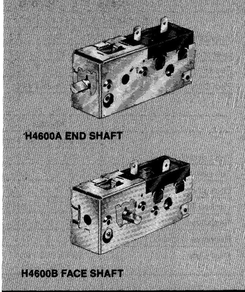
- Shaft for adjusting the control point located on either the end or face of the device.
- Positive ON and OFF setting positions to permit manual operation of the controlled equipment.
SPECIFICATIONS
—————– IMPORTANT——————,
THE SPECIFICATIONS GIVEN IN THIS PUBLICATION DO NOT INCLUDE NORMAL MANUFACTURING TOLERANCES. THEREFORE, THIS UNIT MAY NOT MATCH THE LISTED SPECIFICATIONS EXACTLY. ALSO, THIS PRODUCT IS TESTED AND CA1. IBRATED UNDER CLOSELY CONTROLLED CONDITIONS AND SOME MINOR DIFFERENCES IN PERFORMANCE CAN BE EXPECTED IF THOSE CONDITIONS ARE CHANGED.
MO DELS:
| MODEL | SYSTEM CONTROL | SCALE RANGE (RH) |
| H4600A | Dehumidifier | 20-80% |
| H4600B | Humidifier | 10-60% |
| H66008 | Humidifier | 10-60% |
ELECTRICAL RATINGS (A at 50/60 Hz):
| H4600A | H4600B | |||
| Full Load | 120 Vac | 240 Vac | 120 Vac | 240 Vac |
| 10.0 | 5.0 | 4. | 2. | |
| Locked Rotor | 45.0 | 23. | 26. | 13. |
| Resistive | 12.0 | 6.0 | 12.0 | 6.0 |
| Pilot Duty | 50 VA at 24 Vac to 240 Vac | |||
| H6600B | ||
| Full Load N.O. to C | 120 Vac | 240 Vac |
| 4. | 2. | |
| Full Load N.C. to C | 3.0 | 2. |
| Locked Rotor N.O. to C | 26. | 13. |
| Locked Rotor N.C. to C | 18.0 | 9.0 |
| Resistive N.O. to C | 12.0 | 6.0 |
| Resistive N.C. to C | 3.0 | 2. |
| Pilot Duty | 50 VA a 24 Vac to 240 Vac | |
SE T POINT ADJUSTMENT: External flat shaft on end or face of control.
SW ITCHING: Enclosed, snap-acting.
H4600A-SPST makes on RH increase
H4600B-SPST makes on RH decrease
H6600B-SPDT makes N.C. to C on RH increase, N.O.
to C on RH decrease.
TYP E OF TERMINAL CONNECTION: 1 /4 in.
quick-connect.
SENSING ELEMENT: Nylon ribbon.
DIFFERENT AL: Nonadjustable, 4 to 6 percent RH.
OPERATING TEMPERATURE RANGE: 50 F to 125 F [10 C to 52 C].
SHI PPING AND STORAGE TEMPERATURE: Minus 30 F to plus 150 F [minus 34 C to plus 66 CJ.
MO UNITING MEANS: Metal case and cover, each having two mounting holes that will accept No. 6 sheet metal screws or self-tapping screws. Screw length limited on end shaft model. (See IN STELLA TI ON information.)
DIMENSI ONS: See Fig. 1.
UNDERWIRE TERS LA BORATORI ES INC. COMPONENT RECO GN IZED: File No. E4436, Guide No. XA PX2.
CANADIAN STANDARDS ASSOCIATION COMPONENT RECO GN IZED: File No. LR 60804-1, Class No. 4813 02.
ORDERING INFORMATION
WHEN PURCHASING THIS PRODUCT FROM YOUR DISTRIBUTOR, REFER TO PRICE SHEETS FOR COMPLETE ORDERING NUMBER, OR SPECIFY
- Order number.
- Control shaft on end or face.
IF YOU HAVE ADDITIONAL QUESTIONS, NEED FURTHER INFORMATION, OR WOULD LIKE TO COMMENT ON OUR PRODUCTS OR SERVICES, PLEASE WRITE OR PHONE:
- YOUR LOCAL HONEYWELL RESIDENTIAL SALES OFFICE (CHECK WHITE PA GES OF PHONE DIRECTORY).
- RESIDENTIAL DIVISION CUSTOMER SERVICE
HONEYWELL INC., 1885 DOUGLAS DRIVE NORTH
MINNEAPOLIS, MINNESOTA 55422-4386 (612)542-7500
IN CANADA-HONEYWELL CONTROLS LIMITED/HONEYWELL LIMITEE, 740 ELLESMERE ROAD, SCARBOROUGH, ONTARIO M1P 2V9. INTERNATIONAL SALES AND SERVICE OFFICES IN ALL PRINCIPAL CITIES OF THE WORLD.

FIG. 1-INSTALLATION DIMENSIONS IN in. [mm IN BRACKETS] FOR H4600, H6600.
WHEN INSTALLING THIS PRODUCT …
- Read these instructions carefully. Failure to follow them could damage the product or cause a hazardous condition.
- Check the ratings given in the instructions and on the product to make sure the product is suitable for your application.
- The installer must be a trained, experienced service technician.
- After installation is complete, check out product operation as provided in these instructions.
CAUTION
Disconnect power supply before beginning installation to prevent electrical shock or equipment damage.
MOUNTING
The H4600, H6600 mount in the intake airstream of a humidifier or dehumidifier. Do not mount in outlet air.
Mount to surface with two No. 6 sheet metal screws or self-tapping screws through two holes in the case. For end-sh aft models, mounting screws cannot extend more than 1 /4 in. beyond the mounting surface of the controller.
WIRING
All wiring must comply with local codes and ordinances.

FIG. 2-TYPICAL WIRING DIAGRAM FOR H4600A.

FIG. 3-TYPICAL WIRING DIAGRAM FOR H4600B WITH SINGLE-SPEED FAN MOTOR.

FIG. 4-H6600B INTERNAL SCHEMATIC.
OPERATION
H4600A DEHUMIDIFIER CONTROLLERS
The H4600A switch makes contact on a relative humidity rise to the set point to start the dehumidifier. A decrease in relative humidity to the setpoint minus the differential breaks the switch contact to stop the dehumidifier.
Turn the control knob clockwise


FIG. 5-H4600A STATIONARY SCALE PLATE LA YOUT.
INDEX MARK ON KN OB ROTATES WIT H
ADJUSTMENT SHAFT.
H4600B HUMIDITY CONTROLLERS
The H4600B switch makes contact on a humidity fall to the setpoint minus the differential. In most humidifier systems, the furnace fan must be operating before the humidifier starts. An increase in humidity to the setpoint breaks the switch contacts. (In-room humidifiers, the fan and humidifier operate together.)
Turn control knob clockwise
H6600B SPOT CONTROLLERS
The H6600B controllers are used in humidity control systems requiring spdt switching. The switch makes terminals N.C. and C. on a rise in humidity and terminals C. and N.O. on a fall in humidity.
Turning the control knob counterclockwise


CHECKOUT
Place the system in operation and observe through at least one complete cycle to make certain all components are functioning properly.
Honeywell Inc.
1885 Douglas Drive N.
Golden Valley, MN 55422-4386
International Sales Offices in all principal cities of the world. Manufacturing in Australia, Canada, Finland, France, Germany, Japan, Mexico, Netherlands, Spain, Taiwan, United Kingdom, U.S.A.
PRINTED IN U.S.A.