Honeywell VR8200, VR4200 Combination Gas Controls User Guide


VR8200; VR4200
Combination Gas Controls
This is a legacy product document supported by Resideo.
This product is no longer manufactured.
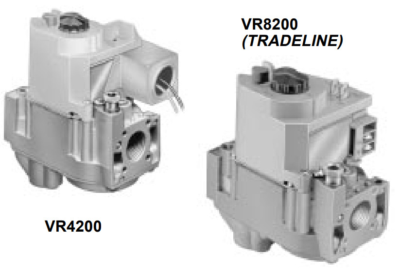

The VR8200 Continuous Pilot Dual Automatic Valve Combination Gas Controls are used in gas-fired, standing pilot appliances. They include a safety shutoff, a manual valve, two automatic operators, a pressure regulator, a pilot adjustment, and a conduit cover (VR4200 only).
- VR8200 for use with 24 Vac heating appliances and VR4200 for use with 120 Vac heating appliances that burn natural or liquefied petroleum (LP) gas.
- Capacity rated at 130 feet 3 /hour at 1-inch WC pressure drop [3.7 m 3 /hr at 0.25 kPa]. The maximum regulated capacity is 200 feet 3 /hour [5.7 meters 3 /hour]. The minimum regulated capacity is 20 feet 3 /hour [0.6 meters 3 /hour].
- Solenoid-operated first automatic valve opens on thermostat call for heat and closes when the call for heat ends.
- The diaphragm-operated second automatic valve opens under the control of the regulator and closes if gas or power supply is interrupted.
- The three-position manual gas control knob has ON, OFF, and PILOT positions.
- A separate reset button must be held down to permit gas flow while lighting the pilot; can be pushed down only in the PILOT position.
- All adjustments, wiring connections, and pilot outlets are accessible from the top of the gas control.
- Compact size.
- Straight-through body pattern; right-angle adapters available for inlet and outlet
- 1/2 in. inlet and 1/2 inch outlet; adapters available for 3/8 or 3/4 inch.
- Adjustable servo regulator effectively maintains almost constant gas output pressure under wide fluctuation in gas supply pressure.
- Inlet and outlet screens included.
- Pilot filter included.
- Wiring terminal block color-coded beige to identify standing pilot models.
- May be installed at any angle between 0 and 90 degrees from the upright position, including vertically.
- 1/4-inch male quick-connect terminals for electrical connections. Combination screw and quick-connect terminals on TRADELINE® models.
- 0° F to +175° F [-18° C to +79° C] temperature range standard; -40° F to +175° F [-40° C to 79° C] available.
- ECO connector included with some models: also available as an accessory.
- Inlet and outlet pressure taps included; both taps accessible from the top of gas control.
- Standard-, slow- and step-opening models available.
- Natural to LP gas conversion kit included with TRADELINE standard and slow-opening models. Natural to LP gas conversion kit available for nonTRADELINE standard and slow-opening models.
- LP to natural gas conversion kit available for standard and slow-opening models.
Specifications
IMPORTANT: The specifications given in this publication do not include normal manufacturing tolerances. Therefore, this unit may not exactly match the listed specifications. Also, this product is tested and calibrated under closely controlled conditions, and some minor differences in performance can be expected if those conditions are changed.
SUPER TRADELINE MODELS
SUPER TRADELINE® controls offer features not avail- able on TRADELINE or standard models, and are designed to replace a wide range of Honeywell and competitive controls.
SUPER TRADELINE model specifications are the same as those of standard models except as noted below.
SUPER TRADELINE MODEL AVAILABLE: VR8200A Continuous Pilot Dual Automatic Combination Gas Control. Models for natural or LP gas.
ADDITIONAL FEATURES:
- Combination 1/4 inch quick-connect and screw terminals (includes convenience terminals).
- One 3/8 inch bushing.
- One 3/4 inch straight flange assembly (with O-ring and screws).
- One tool for flange hex screws.
- One pilot compression fitting.
- One Q340A 36-inch thermocouple with adapters and clip.
TRADELINE MODELS
TRADELINE models are selected and packaged to provide ease of stocking, ease of handling and maximum replacement value. TRADELINE model specifications are the same as those of standard models except as noted below.
TRADELINE MODEL AVAILABLE: VR8200A Continuous Pilot Dual Automatic Combination Gas Control. Models for natural or LP
gas.
ADDITIONAL FEATURES:
- Combination 1/4 inch quick-connect and screw terminals (includes convenience terminals)
- One 3/8 inch bushing
- One 3/4 inch straight flange assembly (with O-ring and screws)
- One tool for flange hex screws
- One pilot compression fitting
STANDARD MODELS
MODEL: VR8200 and VR4200 Continuous Pilot Dual Automatic Valve Combination Gas Controls. For use in standing pilot appliances. See Table 1 for model specifications.
SUPPLY VOLTAGE:
VR4200: 120 Vac, 60 Hz.
VR8200: 24 Vac, 60 Hz.
(50/60 Hz models available on request.)
POWER UNIT:
Hold-in current: 300 mA maximum.
Drop-out current: 250 to 90 mA.
THERMOCOUPLE:
Nominal output: 30 mV (0.018 ohms).
Open Circuit Turndown Voltage: 2 mV.
ELECTRICAL CONNECTIONS (2): 1/4 inch male quick-connects. Two convenience terminals on top of control
(optional). Terminal block color-coded beige.
THERMOSTAT HEAT ANTICIPATOR SETTING:
VR4200: 0.1A
VR8200: 0.5A
TYPE OF GAS: VR8200 and VR4200 set up for natural
gas includes a 393691 LP Conversion Kit. Kit for conversion from LP to natural gas is available for standard and slow opening models. See Accessories.
CAPACITY: 130 feet 3 /hour [4.2 meters 3 /hour]. Capacity is based on 1000 Btu/feet 3, 0.64 specific gravity natural gas at 1-inch water column pressure drop [37.3 MJ/meters 3, 0.64 specific gravity natural gas at 0.25 kPa pressure drop].
The maximum regulated capacity is 200 feet 3 /hour [5.7 meters 3 /hour]. Minimum regulated capacity is 20 feet 3 /hour [0.6 meters 3 /hour]. Use conversion factors in Table 2 to convert to capacities for other gases. The minimum regulated capacity is 40 feet 3 /hour for propane.
Ordering Information
When purchasing replacement and modernization products from your TRADELINE® wholesaler or your distributor, refer to the price sheets for complete ordering number, or specify—
- Order number, SUPER TRADELINE or TRADELINE if desired.
- Natural or LP gas.
- Step pressure on step-opening control.
- Convenience terminals, if desired.
- Accessories, if desired.
- Order separately: pilot burner, thermocouple, transformer, limit controller, and thermostat or controller as required.
If you have additional questions, need further information, or would like to comment on our products or services, please write or phone:
- Your local Honeywell Residential and Building Controls Sales Office (check white pages of your phone directory).
- Residential and Building Controls Division Customer Satisfaction
Honeywell Inc., 1885 Douglas Drive North
Minneapolis, Minnesota 55422-4386 (612) 951-1000
In Canada—Honeywell Limited/Honeywell Limitée, 740 Ellesmere Road, Scarborough, Ontario M1P 2V9. International Sales and Service Offices in all principal cities of the world. Manufacturing in Australia, Canada, Finland, France, Germany, Japan, Mexico, Netherlands, Spain, Taiwan, United Kingdom, U.S.A.
TABLE 1—MODEL SPECIFICATIONS.
| Model No.
Suffix Letter |
Opening
Character- teristic |
Type
of Gas |
Standard Factory
Settings |
Optional Regulator in. wc | Factory Settings
hPa |
Range in. wc | Adjustment
of Field hPa | |
| in. we | hPa | |||||||
| VR8200A, M VR4200A, M |
Standard- opening |
Natural | 4. | 0.9 | 3 to 5 | 0.7 to 1.2 | 3 to 5 | 0.7 to 1.2 |
| LP | 10.0 | 3. | 8 to 12 | 2 to 3 | 8 to 12 | 2 to 3 | ||
| VR8200C, P VR4200C, P |
Step- opening |
Natural | Step-0.7, 0.9, 1.2 or 1.7, as ordered’ Full Rate- 3.5 |
Step-0.17, 0.22, 0.30 or 0.48 as ordered’ Full Rate- 0.9 |
Step-0.7, 0.9, 1.2 or 1.7, as ordered’ Full Rate- 3 to 5 |
Step-0.17, 0.22, 0.30 or 0.48 as ordered’ Full Rate- 0.7 to 1.2 |
Step-none; Full Rate- 3-5 |
Step-none; Full Rate- 0.7 to 1.2 |
| LP | Step-1.4, 2.5, 4.0 or 5.5, as ordered’ Full Rate- 10 |
Step-0.35, 0.62, 0.99 or 1.37, as ordered’ Full Rate- 2.5 |
Step-1.4, 2.5, 4.0 or 5.5, as ordered’ Full Rate- 8 to 12 |
Step-0.35, 0.62, 0.99 or 1.37, as ordered’ Full Rate- 2 to 3 |
Step-none; Full Rate- 8-12 |
Step-none; Full Rate- 2 to 3 | ||
| VR8200H VR4200H |
Slow- opening |
Natural | 4. | 0.9 | 3 to 5 | 0.7 to 1.2 | 3 to 5 | 0.7 to 1.2 |
| us | iu.0 | 2. | 8 to 12 | 2 to .3 | S to 12 | 2 to .3 | ||
| VR8200J | Delayed and Slow-opening |
Natural | 4. | 0.9 | 3 to 5 | 0.7 to 1.2 | 3 to 5 | 0.7 to 1.2 |
| LP | 10.0 | 3. | 8 to 12 | 2 to 3 | 8 to 12 | 2 to 3 | ||
a Step pressure not adjustable.
| Gas | Specific Gravity |
Multiply Listed Capacity by |
| Manufactured | 0.60 | 0.516 |
| Mixed | 0.70 | 0.765 |
| Propane | 1.53 | 1.62 |
BODY PATTERN: Straight-through with 1/2 inch inlet and 1/2 inch outlet. Flanges available for 3/8, 1/2 and 3/4 inch straight and 90° angle connection. See Table 3.
TABLE 3—FLANGE PART NUMBERS.
| Inlet/Outlet
Pipe Size |
Flange
Type |
Part Number | |
| Less Hex
Wrench |
With Hex
Wrench | ||
| 3/8 in. NPT | Straight | 393690-1 | 393690-11 |
| Elbow’ | 393690-2 | 393690-12 | |
| 1/2 in. NPT | Straight | 393690-6 | 393690-16 |
| Elbow’ | 393690-3 | 393690-13 | |
| 3/4 in. NPT | Straight | 393690-4 | 393690-14 |
| Elbowa | 393690-5 | 393690-15 | |
an Elbow (angle) flange cannot provide a right-hand inlet when the ECO connector is used.
NOTE: Flange Kits include one flange with attached O-ring and four mounting screws. TRADELINE kits include a 9/64 in. hex wrench, as noted.
PILOT GAS OUTLET: Compression fitting for 1/4 in. OD tubing.


PRESSURE TAPPING: Inlet and outlet pressure taps accessible from the top of gas control. Taps are 1/8 inch NPT with a plug containing recess for 3/16 inch Allen wrench.
PRESSURE RATING: A.G.A. rating 1/2 psi [3.5 kPa] inlet pressure.
PRESSURE REGULATION: See Table 1. Regulator adjustment is accessible from top of gas control.
MOUNTING: Can be mounted 0 to 90 degrees in any direction from the upright position of the gas control knob, including vertically.
TEMPERATURE RATING:
VR8200A,C,H,J; VR4200A,C,H: 0° F to +175° F [-18° C to +79° C].
VR8200M,P; VR4200M,P: -40° F to +175° F [-40° C to +79° C].
APPROVALS:
American Gas Association design certificate: L2025006.
Canadian Gas Association design certificate: L2025006.
Australian Gas Association design certificate: 4214.
Approved for Delta C applications.
OPTIONAL SPECIFICATIONS:
- Convenience terminals.
ACCESSORIES:
- Flanges, see Table 3.
- 393200-1 ECO Connector.
- 393691 Natural to LP Conversion Kit.
- 394588 LP to Natural Conversion Kit.
- 394349 9/64 inch hex tool for flange assembly screws.
Installation
WHEN INSTALLING THIS PRODUCT…
- Read these instructions carefully. Failure to follow them could damage the product or cause a hazardous condition.
- Check the ratings given in the instructions and on the product to ensure the product is suitable for your application.
- Ensure the installer is a trained, experienced service technician.
- After installation is complete, use these instructions to check out product operation.
FIRE OR EXPLOSION HAZARDS CAN CAUSE PROPERTY DAMAGE, SEVERE INJURY, OR DEATH.
Follow these warnings exactly:

- Disconnect power supply before wiring to prevent electrical shock or equipment damage.
- To avoid the dangerous accumulation of fuel gas, turn off the gas supply at the appliance service valve before starting the installation, and perform Gas Leak Test after completion of installation.
- Do not bend pilot tubing at gas control or pilot burner after compression fitting has been tightened, or gas leakage at the connection may result.
- Always install sediment trap in gas supply line to prevent contamination of gas control.
- Do not force the gas control knob. Use only your hand to push down the reset button or turn the gas control knob. Never use any tools. If the gas control knob or reset button will not operate by hand, the gas control should be replaced by a qualified service technician. Force or attempted repair may result in fire or explosion.
Never apply a jumper across or short the valve coil terminals. This may burn out the heat anticipator in the thermostat.
IMPORTANT: These gas controls are shipped with protective seals over inlet and outlet tappings. Do not remove seals until ready to connect piping.
Follow the appliance manufacturer instructions if available; otherwise, use the instructions provided below.
CONVERTING BETWEEN NATURAL AND LP GAS
FIRE OR EXPLOSION HAZARDS CAN CAUSE PROPERTY DAMAGE, SEVERE INJURY, OR DEATH.
- Do not use a gas control set for natural gas on an LP gas system or a gas control set for LP gas on a natural gas system.
- When making the conversion, the main pilot burner orifices must be changed to meet the appliance manufacturer specifications.
VR8200 and VR4200 gas controls can be converted from one gas to another. To convert from natural gas to LP, use the 393691 LP Conversion Kit that is included with the gas control. To convert from LP to natural gas, use the 394588 Natural Gas Conversion Kit (ordered separately).
VR8200C,P, and VR4200C, P gas controls cannot be converted.
To convert control from one gas to another:
- Turn off the main gas supply to the appliance.
- Remove the regulator cap screw and pressure regulator adjusting screw. See Fig. 2 or 3.
- Remove the existing spring.
- Insert the replacement spring with the tapered end down. See Fig. 4.
- Install the new plastic pressure regulator adjustment screw so that the top of the screw is flush (level) with the top of the regulator. Turn the pressure regulator adjustment screw clockwise
- Check the regulator setting either with a manometer or by clocking the gas meter. Refer to Startup and Checkout section.
- Install the new cap screw.
- Mount conversion label on control.
- Install control and appliance according to appliance manufacturer instructions.


INSTALL ADAPTERS TO GAS CONTROL
If adapters are to be installed on the gas control, mount them as follows:
Flanges
- Choose the appropriate flange for your application.
- Remove seal over gas control inlet or outlet.
- Ensure the O-ring is fitted into the groove of the flange. If the O-ring is not attached or is missing, do not use the flange.
- With O-ring facing the gas control, align the screw holes on the gas control with the holes in the flange. Insert and tighten the screws provided with the flange. See Fig.
- Tighten the screws to 25 inch-pounds of torque to provide a gas-tight seal.
Bushings
- Remove seal over gas control inlet or outlet.
- Apply a moderate amount of good quality pipe compound to bushing, leaving two end threads bare. On LP gas installation, use compound resistant to LP gas. Do NOT use Teflon tape.
- Insert bushing in gas control and thread pipe carefully into bushing until tight.
Complete the instructions below for piping, installing control, connecting pilot tubing, thermocouple and wiring. Make certain the leak test you perform on the control after completing the installation includes leak testing the adapters and screws. If you use a wrench on the valve after flanges are installed, use the wrench only on the flange, not on the control.


USING ADAPTERS TO SOLVE SWING RADIUS PROBLEMS
In some field service applications, it is difficult or impossible to thread the gas control onto the gas supply pipe because of space limitations. Usually this problem can be resolved by using an adapter. The adapter is installed on the end of the supply pipe in place of the gas control, following the same precautions and instructions that are used for installing the gas control. After the adapter is installed, the gas control is attached to the adapter as outlined above. Note that using an adapter increases the overall length of the gas control.
CHOOSE GAS CONTROL LOCATION
Do not locate the gas control where it may be affected by steam cleaning, high humidity, dripping water, corrosive chemicals, dust or grease accumulation, or excessive heat. To ensure proper operation, follow these guidelines:
- Locate gas control in a well-ventilated area.
- Mount gas control high enough above cabinet bottom to avoid exposure to flooding or splashing water.
- Ensure the ambient temperature does not exceed the ambient temperature ratings for each component.
- Cover gas control if the appliance is cleaned with water, steam, or chemicals to avoid dust and grease accumulation.
- Avoid locating gas control where exposure to corrosive chemical fumes or dripping water are likely.
Locate the gas control in the appliance vestibule on the gas manifold. In replacement applications, locate the gas control in the same location as the old gas control.
Install Piping to Gas Control
All piping must comply with local codes and ordinances or with the National Fuel Gas Code (ANSI Z223.1 NFPA No. 54), whichever applies. Tubing installation must comply with approved standards and practices.
- Use new, properly reamed pipe free from chips. If tubing is used, ensure the ends are square, deburred and clean.
All tubing bends must be smooth and without deformation. - Run pipe or tubing to the gas control. If tubing is used, obtain a tube-to-pipe coupling to connect the tubing to the gas control.
- Install sediment trap in the supply line to the gas control. See Fig. 6.
Install Gas Control
- Mount the gas control 0-90 degrees, in any direction, from the upright position of the gas control knob, including vertically.
- Mount the gas control so gas flow is in the direction of the arrow on the bottom of the gas control.
- Thread pipe into gas control. Do not thread pipe too far.
Valve distortion or malfunction can result if the pipe is inserted too deeply into the gas control. Refer to Table 4. - Apply a moderate amount of good quality pipe compound (Do not use Teflon tape) to pipe only, leaving two end threads bare. On LP installations, use compound resistant to LP gas. (See Fig. 7.)
TABLE 4—NPT PIPE THREAD LENGTH IN INCHES.Pipe
SizeThread Pipe
This AmountMaximum Depth The pipe can be Inserted into Control 3/8 9/16 9/16 1/2 3/4 3/4 3/4 13/16 13/16
- Remove seals over gas control inlet and outlet if necessary.
- Connect the pipe to gas control inlet and outlet. Use a wrench on the square ends of the gas control. If an adapter is used, place the wrench on the adapter rather than on gas control.
Refer to Figs. 2, 3 and 8. - Determine if the pilot burner requires a thermocouple with a push-in clip or attachment nut, and attach the correct adapter to the
Q340. - a. For push-in clip-type pilot burners: From beneath, insert the tip of the Q340 into the hole or barrel of the pilot burner. Push in firmly to lock in place.
b. For attachment nut-type pilot burners: From beneath, insert the tip of the Q340 into the hole or barrel in the pilot burner. Engage the threads of the attachment nut and tighten securely. - cut tubing to the desired length and bend as necessary for routing to pilot burner. Do not make sharp bends or deform the tubing. Do not bend tubing at gas control or pilot burner after compression fitting has been tightened, as this may result in a gas leakage at the connection.
- Square off and remove burrs from the end of the tubing.
- Unscrew compression fitting from the pilot outlet (Fig. 2). Slip the compression fitting over the tubing and slide out of the way.
NOTE: When replacing a gas control, cut off the old compression fitting and replace it with the new compression fitting provided on the gas control. Never use the old compression fitting as it may not provide a gas-tight seal. - Push tubing into the pilot gas tapping on the outlet end of the control until it bottoms. While holding tubing all the way in, slide compression fitting into place and engage threads—turn until finger tight. Then tighten one more turn with a wrench. Do not overtighten. Refer to Fig. 9.
- Connect the other end of the tubing to the pilot burner according to pilot burner manufacturer instructions.
- Check the power supply rating on the valve and make sure it matches the available supply. Install thermostat, and other controls as required.
- For the VR4200, when the gas control is installed external to the appliance, install the conduit cover on the conduit fitting. Do not secure conduit cover at this time.
- Connect control circuit to gas control terminals. See Figs. 2, 3 and 11, 12.
NOTE: Use lead wires with insulated terminals. - For the VR4200, make sure the conduit cover is in position and secured to the gas valve with the screw provided. See Fig. 5.
5. Adjust thermostat heat anticipator as instructed in the appliance manual (i.e., usually 0.1A for VR4200 and 0.5A for VR8200).
Connect Supplementary Limit or ECO (If Used) The lead wires from the high limit or ECO must be equipped with insulated 1/4 in. female quick-connect terminals. Leadwire lengths must not exceed the lengths shown in Tables 5 and 6. Connect the high-limit or ECO lead wires to the two terminals on the ECO connector. - POWER SUPPLY. PROVIDE DISCONNECT MEANS AND OVERLOAD PROTECTION AS REQUIRED.
- DO NOT JUMPER THESE TERMINALS. THIS SHORTS VALVE COIL AND MAY BURN OUT THE ANTICIPATOR IN THE THERMOSTAT.
- CONVENIENCE TERMINALS SERVE AS A TIE POINT ONLY. THEY ARE NOT INTERNALLY WIRED TO THE CONTROL CIRCUIT OR TO THE GROUND.
- OPTIONAL HIGH LIMIT.
- Do not force the gas control knob. Use only your hand to push down the reset button or turn the gas control knob. Never use any tools.
- If the gas control knob or reset button will not operate by hand, or if the reset button stays depressed after it is released, the gas control should be replaced by a qualified service technician.
- Paint all pipe connections upstream of the gas control with a rich soap and water solution. Bubbles indicate a gas leak.
- If a gas leak is detected, tighten the pipe connection.
- Stand clear while lighting the main burner to prevent injury caused by hidden gas leaks, which could cause flashbacks in the appliance vestibule. Light the main burner.
- With the main burner in operation, paint all pipe joints (including adapters) and gas control inlet and outlet with rich soap and water solution.
- If another gas leak is detected, tighten adapter screws, joints, and pipe connections.
- Replace the part if the gas leak cannot be stopped.
- Turn the gas control knob clockwise
Wait five minutes to dissipate any unburned gas. Sniff around the appliance near the floor. Do not relight the pilot flame if you smell gas. - Turn the gas control knob counterclockwise
- Hold down the gas control knob about one minute, then release.


Install Thermocouple
The Q340A Thermocouple (with adapters) is provided with SUPER TRADELINE models of the VR8200A. Install the Q340A as
follows:
Connect Pilot Gas Tubing

Connect Thermocouple
Connect thermocouple lead as shown in Fig. 10. This is an electrical connection and must be clean and dry. Never use pipe compound. Tighten only 1/4 turn beyond finger tight to give good electrical continuity. Do not overtighten.
WIRING
Follow the wiring instructions furnished by the appliance manufacturer, if available, or use the general instructions provided below. Where these instructions differ from the appliance manufacturer, follow the appliance manufacturer instructions.
All wiring including 1/4 in. quick-connect terminals, must comply with applicable electrical codes and ordinances.
Disconnect power supply before making wiring connections to prevent electrical shock or equipment damage.
Fig. 10—Installing thermocouple to the power unit.

M2915

Fig. 12—Wiring connections for 120-volt control.

TABLE 5—MAXIMUM LENGTH OF SUPPLEMENTARY LIMIT LEAD WIRES WHEN USING Q340A THERMOCOUPLE.
| I nermocoupie
Length |
Maximum Leadwire Lenith x 2 wires | ||||||
| Awg No. 14 | Awg No. 16 | Awg No. 18 | |||||
| inches | meters | inches | meters | inches | meters | inches | meters |
| 18 | 0.5 | 35 | 0.9 | 22 | 0.6 | 13 | 0.3 |
| 24 | 0.6 | 29 | 0.7 | 18 | 0.5 | 11 | 3 |
| 30 | 0.8 | 23 | 0.6 | 15 | 0.4 | 9 | 0.2 |
| 36 | 0.9 | 17 | 0.4 | 11 | 0.3 | 6 | 0.2 |
| 48 | 1. | DO NOT USE. | |||||
| 60 | 2. | ||||||
TABLE 6—MAXIMUM LENGTH OF SUPPLEMENTARY LIMIT LEADWIRES WHEN USING Q309A THERMOCOUPLE.
| Therm ocouple
Le ngth |
Maximum Leadwire Length x 2 (wires) | ||||||
| Awg No. 14 | Awg No. 16 | Awg No. 18 | |||||
| inches | meters | inches | meters | inches | meters | inches | meters |
| 12 | 0.3 | 47 | 1. | 30 | 0.8 | 18 | 0.5 |
| 18 | 0.5 | 41 | 1.0 | 26 | 0.7 | 16 | 0.4 |
| 24 | 0.6 | 35 | 0.9 | 22 | 0.6 | 14 | 0.4 |
| 30 | 0.8 | 29 | 0.8 | 18 | 0.5 | 11 | 0.3 |
| 36 | 0.9 | 23 | 0.6 | 15 | 0.4 | 9 | 0.2 |
| 40 | 1.0 | 19 | 0.5 | 12 | 0.3 | 7 | 0.2 |
| 48 | 1. | 11 | 0.3 | 7 | 0.2 | ||
| 60 | 2. | DO NOT USE. | |||||
Startup and Checkout
WARNING!
FIRE OR EXPLOSION HAZARDS CAN CAUSE PROPERTY DAMAGE, SEVERE INJURY, OR DEATH.
GAS CONTROL KNOB SETTINGS
The gas control knob has three settings:
OFF: Prevents pilot and main burner gas flow.
PILOT: Permits pilot gas flow only. The gas control knob must be held depressed or the thermocouple must be heated sufficiently to hold the safety control valve open.
ON: Permits main burner and pilot gas flow. Thermostat and gas control main burner gas flow.
NOTE: Gas controls are shipped with the gas control knob in the ON position.
PERFORM GAS LEAK TEST
FIRE OR EXPLOSION HAZARDS CAN CAUSE PROPERTY DAMAGE, SEVERE INJURY, OR DEATH.
Check for gas leaks with rich soap and water solution any time work is done on a gas control.
GAS LEAK TEST
LIGHT THE PILOT BURNER FLAME

- If the pilot flame goes out, turn the gas control knob clockwise
- If the pilot flame remains lit, turn the gas control knob counterclockwise
ADJUST THE PILOT BURNER FLAME
The pilot flame should envelop 3/8 to 1/2 in. [10 to 13 mm] of the thermocouple tip. Refer to Fig. 13. To adjust the pilot flame:
- Remove the pilot adjustment cover screw. Refer to Fig. 2.
- Turn the inner adjustment screw clockwise
- Always replace the cover screw after adjustment and tighten firmly to assure proper operation.
LIGHT MAIN BURNER
Follow the appliance manufacturer instructions or set the thermostat setting above room temperature to call for heat.

CHECK AND ADJUST GAS INPUT TO THE MAIN BURNER
CAUTION
- Do not exceed the input rating stamped on the appliance nameplate or manufacturer-recommended burner orifice pressure for the size orifice(s) used. Assure the main burner primary air supply is properly adjusted for complete combustion (refer to the appliance manufacturer instructions).
- IF CHECKING GAS INPUT BY CLOCKING THE GAS METER:
• Assure that the only gas flow through the meter is that of the appliance being tested.
• Assure that other appliances are turned off and their pilot burners are extinguished (or deduct their gas consumptions from the meter reading).
• Convert the flow rate to Btuh as described in the Gas Controls Handbook (form 70-2602) and compare to the Btuh input rating on the appliance nameplate. - IF CHECKING GAS INPUT WITH A MANOMETER (PRESSURE GAUGE):
• Assure the gas control knob is in the PILOT position before removing the outlet pressure tap plug to connect the manometer.
• Turn the gas control knob back to PILOT when removing the manometer and replacing outlet pressure tap plug.
• Shut off the gas supply at the appliance service valve or, for LP gas, at the gas tank before removing the outlet pressure tap plug and before disconnecting the manometer and replacing the outlet pressure tap plug.
• Perform the Gas Leak Test at the inlet pressure tap plug.
Standard-Opening and Slow-Opening Pressure Regulator
- The gas control outlet pressure should match the manifold pressure listed on the appliance nameplate.
- With the main burner operating, check the gas control flow rate using the meter clocking method or check the gas pressure using a manometer connected to the gas control outlet pressure tap. Refer to Figs. 2 and 3.
- If necessary, adjust the pressure regulator to match the appliance rating. Refer to Table 7 or 8 for the factory-set nominal outlet pressures and adjustment ranges.
a. Remove the pressure regulator adjustment cap and screw.
b. Using a screwdriver, turn the inner adjustment screw clockwise
c. Always replace the cap screw and tighten firmly to assure proper operation. - If the desired outlet gas pressure or gas flow rate cannot be achieved by adjusting the gas control, check the gas control inlet pressure using a manometer at the inlet pressure tap. If the inlet pressure is in the normal range (refer to Table 7 or 8), replace the gas control. Otherwise, take the necessary steps to provide proper gas pressure to the gas control.
Step-Opening Pressure Regulator and Delayed and Step-Opening Pressure Regulator
- The gas control outlet pressure should match the manifold pressure listed on the appliance nameplate.
- With the main burner operating, check the gas control flow rate using the meter clocking method or check the gas pressure using a manometer connected to the gas control outlet pressure tap. Refer to Figs. 2 and 3.
- If necessary, adjust the pressure regulator to match the appliance rating. Refer to Table 7 or 8 for factory-set nominal outlet pressures and adjustment ranges.
a. Remove the pressure regulator adjustment cap screw.
b. Using a screwdriver, turn the inner adjustment screw clockwise to increase or counterclockwise to decrease the main burner gas pressure.
c. Always replace the cap screw and tighten firmly to assure proper operation. - If desired outlet pressure or flow rate cannot be achieved by adjusting the gas control, check the inlet pressure using a manometer at the inlet pressure tap or upstream of the gas control. If the inlet pressure is in the normal range (refer to Table 7 or 8), replace the existing gas control. Otherwise, take the necessary steps to provide proper gas pressure to the gas control.
- Carefully check the main burner light off at the step pressure. Ensure the main burner lights smoothly and without a flashback to the orifice and that all ports remain lit. Cycle the main burner several times, allowing at least 30 seconds between cycles for the regulator to resume the step function. Repeat after allowing the main burner to cool. Readjust the full rate outlet pressure if necessary to improve light off characteristics.
TABLE 7—PRESSURE REGULATOR SPECIFICATION PRESSURES IN INCHES WC.
| Model | Type of Gas | Nominal Inlet
Pressure Range |
Outlet Pressure | |||
| Nominal Factory Setting | Setting Range | |||||
| Step | Full
Rate |
Step | Full
Rate | |||
| Standard,Slow- opening | NATURAL | 5.0 – 7.0 | — | 4. | — | 3.0 – 5.0 |
| LP | 12.0 – 14.0 | — | 10.0 | — | 8.0 – 12.0 | |
| Step-opening | NATURAL | 5.0 – 7.0 | 0.9 | 4. | — | 3.0 – 5.0 |
| LP | 12.0 – 14.0 | 2. | 10.0 | — | 8.0 – 12.0 | |
TABLE 8—PRESSURE REGULATOR SPECIFICATION PRESSURES IN kPa.
| Model | Type of Gas | Nominal Inlet
Pressure Range |
Outlet Pressure | |||
| Nominal Factory Setting | Setting Range | |||||
| Step | Full
Rate |
Step | Full
Rate | |||
| Standard, Slow- opening |
NATURAL | 1.2 – 1.7 | — |
0.9 | — |
0.7 – 1.2 |
| LP | 2.9 – 3.9 | 3. | — | 2.0 – 3.0 | ||
| Step- opening | NATURAL | 1.2 – 1.7 | 0.2 | 0.9 | — | 0.7 – 1.2 |
| LP | 2.9 – 3.9 | 0.9 | 3. | — | 2.0 – 3.0 | |
CHECK SAFETY SHUTDOWN PERFORMANCE
WARNING!
FIRE OR EXPLOSION HAZARDS CAN CAUSE PROPERTY DAMAGE, SEVERE INJURY, OR DEATH.
Perform the safety shutdown test any time work is done on a gas system.
- Place gas control knob in PILOT position. The main burner should go off and the pilot should remain lit.
- Extinguish pilot flame. Pilot gas flow should stop within 2-1/2 minutes. Safety shutoff or pilot gas proves complete shutdown since the safety shutoff valve permits main burner and pilot gas flow.
- Relight pilot burner and operate the system through one complete cycle to assure all controls operate properly.
Maintenance
Regular preventive maintenance is important in applications that place a heavy load on system control such as in the commercial looking and agricultural and industrial industries because:
- In many such applications, particularly commercial cooking, the equipment operates 100,000-200,000 cycles per year. Such heavy cycling wears out the gas control in one to two years.
- Exposure to water, dirt, chemicals, and heat can damage the gas control and shut down the control system. The maintenance program should include regular checkout of the gas control, see the Startup and Checkout section, and the control system as described in the appliance manufacturer literature. Maintenance frequency must be determined individually for each application. Some considerations are:
- Cycling frequency. Appliances that may cycle 120,000 times annually should be checked monthly.
- Intermittent use. Appliances that are used seasonally should be checked before shutdown and again before the next use.
- A consequence of unexpected shutdown. Where the cost of an unexpected shutdown would be high, the system should be checked more ften.
- Dusty, wet, or corrosive environment. Since these environments can cause the gas control to deteriorate more rapidly, the system should e checked more often. Gas valves exposed to high ammonia conditions, i.e., those used in greenhouses or animal barns may fail in one or two years. Contact your Honeywell sales representative to request a gas valve with corrosion-resistant construction. The gas control should e replaced if:
- It does not perform properly on checkout or troubleshooting.
- The gas control knob is hard to turn or push down, or it fails to pop back up when released.
- The gas control is likely to have operated for more than 200,000 cycles.
Operation
The VR8200, VR4200 gas controls provide 3-position (OFF-PILOT-ON) manual control of gas flow. The OFF position prevents pilot and main burner gas flow. The PILOT position allows pilot burner gas flow only. The ON position allows pilot burner and main burner gas low under control of the thermostat and the two automatic valves. When the thermostat calls for heat, the first automatic valve and the second automatic valve operator open. The second automatic valve diaphragm, controlled by the servo pressure regulator, opens and adjusts gas flow as long as the system is powered and the pilot is burning. The servo pressure regulator monitors outlet pressure to provide n even the main burner gas flow. Loss of power closes the automatic valves, but leaves the pilot lit, ready to return to normal service when power is restored. Loss of pilot flame or flame too small to reliably light the main burner closes the safety shutoff valve and the second automatic valve. The gas control must be manually reset. Gas control operation is described in more detail below.
VALVE POSITION DURING THERMOSTAT OFF
CYCLE
The valve is positioned as shown in Fig. 14 when the:
- the manual gas control knob is in the ON position.
- The pilot burner is lit.
- the thermostat is not calling for heat.
The power unit holds the safety shutoff valve disc off its seat, so gas can flow into the control. Pilot gas flows through a port in the ushing around the reset button shaft to the pilot burner. The first automatic valve is closed. The second automatic valve operator is de- energized, closing the channel to the pressure regulator, and opening a channel to the underside of the second automatic valve diaphragm. The combination of spring pressure under the second automatic valve diaphragm and the lack of outlet pressure holds the diaphragm firmly closed. The main burner gas flow is blocked by both automatic valves.
WHEN THE THERMOSTAT CALLS FOR HEAT
The gas control allows pilot and main burner gas flow during the thermostat ON cycle, as shown in Fig. 15. When the thermostat calls for eat, the first automatic valve and the second automatic valve operator are energized. The first automatic valve opens, and the second automatic valve operator valve disc is lifted off its seal. This diverts gas flow from the automatic valve diaphragm and causes a reduction of pressure on the underside of this diaphragm. The reduced pressure on the bottom of the automatic valve diaphragm repositions the diaphragm downward away from the valve seat, allowing main burner gas flow.
Standard Opening Pressure Regulation (VR8200A,M,
and VR4200A, M)
During the ON cycle, the servo pressure regulator provides close control of outlet pressure, even if inlet pressure and flow rate vary widely. ny outlet pressure change is immediately reflected back to the pressure regulator diaphragm, which repositions to change the flow rate through the regulator valve and, thus, through the diaphragm-operated automatic valve. If outlet pressure begins to rise, the pressure regulator the diaphragm moves slightly higher, allowing less gas flow to the gas control outlet. This increases gas pressure under the automatic valve and repositions the valve disc closer to the seat. Thus the flow of gas through the second automatic valve is reduced, and outlet pressure falls to the desired level. If outlet pressure begins to fall, the pressure regulator diaphragm moves slightly lower allowing ore to flow to the gas control outlet. This decreases gas pressure under the second automatic valve diaphragm and repositions the valve disc further from the seat. Thus, the flow of gas through the second automatic valve is increased, and outlet pressure rises to the desired level.
Slow-Opening Pressure Regulation (VR8200H and
VR4200H); Delayed and Slow-opening Regulation
(VR8200J)
Slow-opening gas controls function the same as standard models except that when the thermostat calls for heat, the second automatic alve pens gradually. The opening is slowed because a gas flow restrictor in the passage from the second automatic operator slows the rate at hich gas pressure is reduced under the second automatic valve diaphragm after the automatic operator opens. Outlet pressure to the main burner increases gradually from 0 in. wc [0 kPa] to rated output pressure within 3-6 seconds (for an 80,000 Btuh furnace at 7 in. wc [1.8 kPa] inlet pressure and 3.5 in. wc [0.9 kPa] outlet pressure). VR8200J has a six-second delay from when the thermostat calls for heat until the main gas valve opens.
Step-Opening Pressure Regulation (VR8200C,P and
VR4200P)
Step-opening gas controls actually combine two pressure regulators, one for the low pressure and one for the full-rate pressure. When the thermostat calls for heat, the automatic operator valve disc opens. The low-pressure regulator maintains outlet pressure at the preset step rate for several seconds. Then the regulator valve is forced fully open by the timing diaphragm, which is operated by bleed gas. When the ow pressure regulator is fully open, the high-pressure regulator maintains the desired full-rate outlet pressure as described for the standard regulator.
The step model requires approximately 60 seconds to reset once the main burner goes off. If it is re-energized within 60 seconds, it may bypass or shorten the length of the low-pressure step. The burner may relight at the full flow rate.
WHEN THE CALL FOR HEAT ENDS
When the call for heat ends, the first automatic valve and the second automatic valve operator close, bypassing the regulator(s) and hutting ff the main burner. As the pressure inside the gas control and underneath the automatic valve diaphragm equalizes, spring pressure closes the second automatic valve to provide a second barrier to gas flow.


SAFETY SHUTOFF OPERATION
In the safety shutoff position, pilot and main burner gas flow is permitted.
Safety shutoff occurs:
- When the gas control knob is manually turned to OFF.
- When the pilot goes out or becomes too small to sustain normal ignition.
Gas Control Knob Turned to OFF
When the gas control knob is turned to OFF, it pulls up and locks the reset button, and closes the first automatic valve. The small valve seat attached to the reset button closes and shuts off the pilot gas flow. When the pilot goes out, the thermocouple current drops and the power unit drops out, closing the safety shutoff valve. This shuts off the pilot and main burner gas flow. With the loss of outlet pressure, the second automatic valve closes and is held closed by spring pressure on the diaphragm.
When Pilot Flame Goes Out
When the pilot flame goes out or is too small to reliably light the main burner, thermocouple output drops below the power unit hold-in valve. The power unit drops out, closing the safety valve and stopping all gas flow through the control.
With the loss of outlet pressure, the second automatic valve closes and is held closed by spring pressure on the diaphragm.
Service
WARNING!
FIRE OR EXPLOSION HAZARDS CAN CAUSE PROPERTY DAMAGE, SEVERE INJURY OR DEATH.
Do not disassemble the gas control; it contains no replaceable components. Attempted disassembly or repair may damage the gas control.
Do not apply a jumper across or short the valve coil terminals. This may burn out the heat anticipator in the thermostat or damage the DI module.
IMPORTANT: Allow 60 seconds after shutdown before reenergizing the step-opening model to assure light off at step pressure.
IF THE PILOT BURNER FLAME WILL NOT LIGHT
- Assure the main gas supply valve is open and the pilot gas supply line is purged of air.
- Attempt to light pilot burner flame following procedures in the Light the Pilot Burner Flame section. If pilot burner flame still will not light:
a. Check the pilot gas adjustment screw. If closed, readjust the pilot flame. Refer to the Adjust the Pilot Burner Flame section.
b. Perform the Gas Leak Test at the compression fitting. If a gas leak is detected, replace the old compression fitting or tighten the newly installed one. Refer to Fig. 9.
c. Assure the pilot burner tubing or pilot burner orifice is not clogged.
IF THE PILOT BURNER FLAME GOES OUT WHEN THE GAS CONTROL KNOB IS RELEASED
- Assure the gas control knob is held in at least one minute to allow the thermocouple time to heat.
- Check the pilot burner flame adjustment. Refer to the Adjust the Pilot Burner Flame section.
- Check the wiring between the thermocouple and the gas control valve operator.
- Assure thermocouple connection to the power unit is tightened 1/4 turn beyond finger tight.
- If pilot burner flame still goes out, measure the open and closed thermocouple output voltage. Compare it to the acceptable range charts in the thermocouple specifications or in the Gas Controls Handbook. Replace the thermocouple if voltages are outside the acceptable range.
- Check the power unit resistance. If above 11 ohms, replace the gas control.
IF THE MAIN BURNER WILL NOT COME ON WITH A CALL FOR HEAT
- Assure the gas control knob is in the ON position.
- Adjust the thermostat several degrees above room temperature.
- Use an ac voltmeter to measure the voltage across terminals TH and TR. If:
a. No voltage is present, check the control circuit for proper operation.
b. Correct voltage (VR8200, 24 Vac; VR4200, 120 Vac) is present, but first operator did not click open, check for excessive inlet gas pressure. If inlet gas pressure is correct, replace the gas control. - Measure the open and closed thermocouple output voltages and compare to the acceptable range charts in the thermocouple specifications or in the Gas Controls Handbook. Replace the thermocouple if voltages are outside the acceptable range.
IF THE MAIN BURNER IS OVERFIRING
Adjust the gas control pressure regulator to the correct pressure. If the regulator cannot be adjusted and supply pressure is in the normal range, replace the gas control.
INSTRUCTIONS TO THE HOMEOWNER FOR YOUR SAFETY, READ BEFORE OPERATING
IF YOU DO NOT FOLLOW THE WARNINGS BELOW AND THE LIGHTING INSTRUCTIONS EXACTLY, A FIRE OR EXPLOSION CAN RESULT WITH PROPERTY DAMAGE, PERSONAL INJURY OR LOSS OF LIFE.
- Before lighting, smell all around the appliance area for gas. If the appliance uses LP (bottled) gas, be sure to smell next to the floor because LP gas is heavier than air. If you smell gas, immediately shut off the manual valve in the gas piping to the appliance or, on LP, at the tank. Do not try to light any appliance. Don’t touch any electrical switch or use the phone.
Leave the building and call your gas supplier. If your gas supplier cannot be reached, call the fire department. - Do not force the gas control knob on the appliance. Use only your hand to push down the reset button or turn the gas control knob. Never use any tools. If the knob or reset button will not operate by hand, replace the control using a qualified service technician. Force or attempted repair can result in fire or explosion.
The gas control must be replaced if it has been flooded with water. Call a qualified service technician. - If the red reset button stays depressed after it is released, replace the gas control.
- Gas control is a safety device. It must be replaced in case of any physical damage such as bent terminals, missing or broken parts, stripped threads, or evidence of exposure to heat.
IMPORTANT: Follow the operating instructions provided by the manufacturer of your heating appliance. The information below will be of assistance in a typical control application, but the specific controls used and the procedures outlined by the manufacturer of the appliance may differ and require special instructions.
TO LIGHT THE PILOT BURNER
STOP! Read the safety information in the WARNING.
This appliance has a pilot burner, which must be lit by hand. If the pilot flame has gone out, follow these instructions exactly:
- Set the thermostat to the lowest setting and shut off the electric power to the appliance.
- Remove the burner access panel if provided on your appliance.
- Turn the gas control knob (Figs. 2 or 3) clockwise
- Wait five minutes to allow any gas in the combustion chamber to vent. If you then smell gas in the appliance area or near the floor in an LP installation, immediately shut off the manual valve in the gas piping to the appliance or, with LP, shut off at the tank. Do not touch any electrical switch or use the phone. Leave the building and call your gas supplier. If your gas supplier cannot be reached, call the fire department. Failure to do so may result in fire or explosion.
- If you do not smell gas, turn the knob on gas control counterclockwise
- Push and hold down the red reset button (Figs. 2 or 3) while you light the pilot burner. Continue to hold down the reset button for about one minute after the pilot is lit. Release button; the pilot should remain lit. If it goes out, repeat steps 36. If the reset button does not pop up when released, stop immediately and call your service technician or gas supplier.
If the pilot will not remain lit after several tries, turn the gas control knob to OFF and call your service technician or gas supplier. - When the pilot remains lit, turn the gas control knob counterclockwise
- Replace the burner access panel.
- Turn on Power.
- Set thermostat to the desired temperature.
TO TURN OFF THE APPLIANCE
VACATION SHUTDOWN: Turn gas control knob clockwise
COMPLETE SHUTDOWN: Turn the gas control knob clockwise
Home and Building Control
Honeywell Inc.
1985 Douglas Drive North
Golden Valley, Minnesota 55422
Home and Building Control
Honeywell Limited—Honeywell Limitée
740 Ellesmere Road
Scarborough, Ontario
M1P 2V9
Helping You Control Your World

Printed in the U.S.A.