Honeywell H1008A,D Automatic Humidity Controls User Guide


Honeywell H1008A,D Automatic Humidity Controls

APPLICATION
The H1008A,D Automatic Humidity Controls with HumidiCalc+™ Software are duct mounted and provide automatic, low voltage, electronic control of by-pass flow-through, powered flow-through, steam and drum humidifiers in central heating systems. The H1008D also controls heat/energy recovery units and dehumidifiers. The H1008A,D are designed to automatically adjust the humidity level based on indoor temperature and humidity, inferred or measured outdoor temperature and the setting of the frost factor dial. The frost factor setting is used to maintain a comfortable humidity level in the home while reducing moisture condensation on inside windows. The HumidiCalc+™ Software infers the outdoor temperature by monitoring the equipment cycles and eliminates the need for an outdoor temperature sensor when used on single-stage gas or oil furnaces. With the use of the C7089H Outdoor Temperature Sensor (purchased separately), the H1008A,D also provide automatic humidity control in heat pump and multi-stage systems.
® U.S. Registered Trademark
Copyright © 1999 Honeywell Inc. • All Rights Reserved
FEATURES
- The H1008A,D provides automatic control for by-pass flow-through, powered flow-through, steam and drum humidifiers in central heating systems.
- The H1008D also provides automatic control for dehumidification using heat/energy recovery ventilators or dehumidifiers.
- Patented Honeywell HumidiCalc+™ Software eliminates the need for an outdoor sensor on the most common single-stage, gas or oil forced air equipment.
- Combination temperature and humidity sensor accurately determines the dewpoint at the control location.
- Equipment connection can eliminate the need for a current sensing relay on the blower.
- Simple duct mount requires only a 3/4 in. (19 mm) circular duct opening for sensors.
- With the use of the C7089H Outdoor Temperature Sensor, the H1008A,D also provides automatic humidity control in heat pump and multi-stage systems.
- Automatically adjusts humidity level based on the frost factor set by the homeowner.
- Frost factor input allows for variances in furnace oversizing, window insulation and average daily climate temperature.
- System status light indicates normal operation, test mode and fault indication.
SPECIFICATIONS
IMPORTANT
The specifications given in this publication do not include normal manufacturing tolerances. Therefore, this unit may not exactly match the listed specifications. Also, this product is tested under closely controlled conditions and some minor differences in performance can be expected if those conditions are changed.
TRADELINE® Models:
H1008A,D Automatic Humidity Control with HumidiCalc+Software: Includes template and four mounting screws.
Electrical Ratings:
Power Supply: 18-30 Vac, 60 Hz.
Power Consumption: 2.5 VA at 27 Vac.
Relay Contacts:
Inductive: 2A full load, 10A locked rotor at 24 Vac.
Resistive: 2A
Thermostat/Furnace Load: 11 mA maximum at 24 Vac.
Temperature Ratings:
Operating Range: 45° to 88°F (7° to 31°C).
Storage Range: -40°F to 150°F (-40° to 66°C).
Humidity Ratings:
Always dehumidifies at 58° and above dewpoint. Allows humidification/dehumidification at 50°F and below dewpoint. Does not allow humidification when dewpoint is above 50°F.
Dimensions:
Refer to Fig. 1.
Accessories:
C7089H Outdoor Temperature Sensor.
ORDERING INFORMATION
When purchasing replacement and modernization products from your TRADELINE® wholesaler or distributor, refer to the TRADELINE® Catalog or price sheets for complete ordering number. If you have additional questions, need further information, or would like to comment on our products or services, please write or phone:
- Your local Home and Building Control Sales Office (check white pages of your phone directory).
- Home and Building Control Customer Relations Honeywell Inc., 1985 Douglas Drive North Minneapolis, Minnesota 55422-4386. In Canada—Honeywell Limited/Honeywell Limitée, 35 Dynamic Drive, Scarborough, Ontario M1V 4Z9.
International Sales and Service Offices in all principal cities of the world. Manufacturing in Australia, Canada, Finland, France, Germany, Japan, Mexico, Netherlands, Spain, Taiwan, United Kingdom, U.S.A.

INSTALLATION
When Installing this Product…
- Read these instructions carefully. Failure to follow them could damage the product or cause a hazardous condition.
- Check the ratings given in the instructions and on the product to make sure the product is suitable for your application.
- Installer must be a trained, experienced service technician.
- After installation is complete, check out product operation as provided in these instructions.
CAUTION
Voltage Hazard. Power supply can cause electrical shock. Disconnect power supply before beginning installation.
Location and Mounting
H1008A,D Automatic Humidity Control
IMPORTANT
Do not install H1008 on supply air. Temperatures in excess of 120°F cause the control to go into error mode. If mounting near an elbow area, keep the control 6 in. (152 mm) upstream from the elbow so that the humidity and temperature sensor is exposed to the normal airflow (Fig. 2).
Locate the control at least 12 in. (305 mm) upstream from the humidifier (or dehumidifion/ventilator supply air) in the return air duct where it can be exposed to the air stream of the return air. See Fig. 2.

Use the following procedure to mount the H1008A,D in the return air duct:
- Remove the cover by placing your thumb in the bottom notch between the cover and the base and pulling out and up. See Fig. 3.
- Drill 3/4 in. (19 mm) circular opening for the projection on the back of the base. See Fig. 4. Place the device on the duct and mark the mounting holes, or screw in the self-tapping screws.
NOTE: Be sure the sheet metal surface is flat after drilling and cutting holes. - Mount the base on the duct using the four mounting screws provided. Tighten the screws firmly so the space between the base and the duct is seated. See Fig. 4.
- Run a low voltage wire from the humidifier and equipment to the control terminals. See Fig. 6-11. Use either straight in or wraparound wiring connections. See Fig. 5.
- Snap the cover onto the base.


C7089H Outdoor Temperature Sensor
NOTE: The C7089H Outdoor Temperature Sensor is required only when using the H1008A control with heat pump, multi-stage equipment or multi-zone applictions.
Mount the sensor (purchased separately):
- out of direct sunlight on the North side of the house.
- at least three feet from dryer vents or other vents.
- above the expected snow line where ice and debris cannot cover it.
Use the following procedure for mounting:
- Place the sensor in the clamp provided.
- Insert the screw provided through the holes in the clamp and fasten the sensor in place.
WIRING
CAUTION
Voltage Hazard. Power supply can cause electrical shock and injury. Disconnect power supply before installation or servicing. All wiring must comply with applicable local codes, ordinances and regulations.
IMPORTANT
Use 18- to 22-gauge insulated wire for proper wiring. Stranded-tinned wire is recommended. To wire the Automatic Humidity Control:
IMPORTANT: When installing a steam-powered humidifier, be sure to cut the factory-installed steam jumper wire for proper operation.
- Connect 24 Vac power to the 24 Vac HOT and COM terminals on the H1008A,D.
- Connect the humidifier to the two HUM terminals on the H1008A,D as shown in Fig. 6 through 11.
- In furnace systems with two transformers, connect CG to the cooling system transformer common and connect CW to the heating transformer common. Be sure G and W connect to the R terminals of both transformers. (If only one transformer is used, leave the jumper on CG and CW.) See Fig. 6.
- To Wire the C7089H Outdoor Temperature Sensor, wire the sensor to the two OUT terminals on the H1008A,D.

- POWER SUPPLY. PROVIDE DISCONNECT MEANS AND OVERLOAD PROTECTION AS REQUIRED.
- IN SINGLE TRANSFORMER SYSTEMS, JUMPER CG AND CW.
IMPORTANT: For proper wiring, use 18- to 22-gauge wire. Stranded-tinned wire with a maximum length of 300 ft.(91m) is recommended.
NOTE: Connect the humidistat to the furnace for two reasons:
- The control can determine the outdoor temperature.
- The control knows when the furnace blower is operating, eliminating the need for current sensing relays.

- POWER SUPPLY. PROVIDE DISCONNECT MEANS AND OVERLOAD PROTECTION AS REQUIRED.
- 24V WIRING.
- TO PROVIDE HUMIDITY IN FAN MODE, CONNECT G AND CG TERMINALS TO FAN RELAY.
- IN TWO TRANSFORMER SYSTEMS, REMOVE CW/CG FACTORY INSTALLED JUMPER.
- IF USING OUTDOOR TEMPERATURE SENSOR, REMOVE FACTORY INSTALLED JUMPER.
- ISOLATED RELAY CONTACTS.
- HEAT ONLY APPLICATION SHOWN. SIMILAR WIRING REQUIRED IN HEAT AND COOL SYSTEM WITH ONE OR TWO TRANSFORMERS. WHEN HEAT AND FAN OPERATE SIMULTANEOUSLY WITH ONE RELAY, JUMP W TO G AND JUMP CG TO CW.
- POWER SHOULD BE APPLIED TO THIS CONTROL AT ALL TIMES. DO NOT USE FAN BOARD HUMIDISTAT CONTACTS OR CURRENT SENSING RELAY.
- CUT JUMPER FOR DEHUMIDIFIER APPLICATION. (DO NOT CUT FOR VENTILATION SYSTEM.)
- DEHUM TERMINALS SWITCH LOW VOLTAGE DEHUMIDIFIERS, HEAT/ENERGY RECOVERY UNITS OR EXTERNAL CONTACTORS THAT SWITCH HIGH VOLTAGE DEHUMIDIFIERS.
- JUMPER AND DEHUM TERMINALS NOT PRESENT ON H1008A MODEL.

- POWER SUPPLY. PROVIDE DISCONNECT MEANS AND OVERLOAD PROTECTION AS REQUIRED.
- 24V WIRING.
- TO PROVIDE HUMIDITY IN FAN MODE, CONNECT G AND CG TERMINALS TO FAN RELAY.
- IN TWO TRANSFORMER SYSTEMS, REMOVE CW/CG FACTORY INSTALLED JUMPER.
- IF USING OUTDOOR TEMPERATURE SENSOR, REMOVE FACTORY INSTALLED JUMPER.
- ISOLATED RELAY CONTACTS.
- HEAT ONLY APPLICATION SHOWN. SIMILAR WIRING REQUIRED IN HEAT AND COOL SYSTEM WITH ONE OR TWO TRANSFORMERS. WHEN HEAT AND FAN OPERATE SIMULTANEOUSLY WITH ONE RELAY, JUMP W TO G AND JUMP CG TO CW.
- POWER SHOULD BE APPLIED TO THIS CONTROL AT ALL TIMES. DO NOT USE FAN BOARD HUMIDISTAT CONTACTS OR CURRENT SENSING RELAY.
- CUT JUMPER FOR DEHUMIDIFIER APPLICATION. (DO NOT CUT FOR VENTILATION SYSTEM.)
- DEHUM TERMINALS SWITCH LOW VOLTAGE DEHUMIDIFIERS, HEAT/ENERGY RECOVERY UNITS OR EXTERNAL CONTACTORS THAT SWITCH HIGH VOLTAGE DEHUMIDIFIERS. JUMPER AND DEHUM TERMINALS NOT PRESENT ON H1008A MODEL.

- POWER SUPPLY. PROVIDE DISCONNECT MEANS AND OVERLOAD PROTECTION AS REQUIRED.
- 24V WIRING.
- REFER TO THE STEAM HUMIDIFIER INSTALLATION INSTRUCTIONS TO WIRE SYSTEM FAN.
- CUT JUMPER FOR STEAM HUMIDIFIER CONTROL.
- FAN TERMINALS G AND CG NOT USED IN THIS APPLICATION.
- EXTERNAL TRANSFORMER NOT PROVIDED.
- IF OUTDOOR TEMPERATURE SENSOR IS NOT USED, WIRE HEAT TERMINALS W AND CW TO FURNACE.
- IF USING OUTDOOR TEMPERATURE SENSOR, REMOVE FACTORY INSTALLED JUMPER.
- ISOLATED RELAY CONTACTS.
- HEAT ONLY APPLICATION SHOWN. SIMILAR WIRING REQUIRED IN HEAT AND COOL SYSTEM WITH ONE OR TWO TRANSFORMERS. WHEN HEAT AND FAN OPERATE SIMULTANEOUSLY WITH ONE RELAY, JUMP W TO G AND JUMP CG TO CW.
- POWER SHOULD BE APPLIED TO THIS CONTROL AT ALL TIMES. DO NOT USE FAN BOARD HUMIDISTAT CONTACTS OR CURRENT SENSING RELAY.
- CUT JUMPER FOR DEHUMIDIFIER APPLICATION. (DO NOT CUT FOR VENTILATION SYSTEM.)
- DEHUM TERMINALS SWITCH LOW VOLTAGE DEHUMIDIFIERS, HEAT/ENERGY RECOVERY UNITS OR EXTERNAL CONTACTORS THAT SWITCH HIGH VOLTAGE DEHUMIDIFIERS.
- JUMPER AND DEHUM TERMINALS NOT PRESENT ON H1008A MODEL.

- POWER SUPPLY. PROVIDE DISCONNECT MEANS AND OVERLOAD PROTECTION AS REQUIRED.
- 24V WIRING.
- TO PROVIDE HUMIDITY IN FAN MODE, CONNECT G AND CG TERMINALS TO FAN RELAY.
- IN TWO TRANSFORMER SYSTEMS, REMOVE CW/CG FACTORY INSTALLED JUMPER.
- IF USING OUTDOOR TEMPERATURE SENSOR, REMOVE FACTORY INSTALLED JUMPER.
- ISOLATED RELAY CONTACTS.
- HEAT ONLY APPLICATION SHOWN. SIMILAR WIRING REQUIRED IN HEAT AND COOL SYSTEM WITH ONE OR TWO TRANSFORMERS. WHEN HEAT AND
- FAN OPERATE SIMULTANEOUSLY WITH ONE RELAY, JUMP W TO G AND JUMP CG TO CW.
- POWER SHOULD BE APPLIED TO THIS CONTROL AT ALL TIMES. DO NOT USE FAN BOARD HUMIDISTAT CONTACTS OR CURRENT SENSING RELAY.
- CUT JUMPER FOR DEHUMIDIFIER APPLICATION. (DO NOT CUT FOR VENTILATION SYSTEM.) DEHUM TERMINALS SWITCH LOW VOLTAGE DEHUMIDIFIERS, HEAT/ENERGY RECOVERY UNITS OR EXTERNAL CONTACTORS THAT SWITCH HIGH VOLTAGE DEHUMIDIFIERS.
- JUMPER AND DEHUM TERMINALS NOT PRESENT ON H1008A MODEL.

SETTINGS
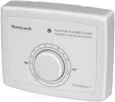
Adjustment
The H1008A,D Automatic Humidity Control with HumidiCalc+™ Software is designed to provide an optimal 50°F (10°C) dewpoint and automatically adjusts the humidity level to prevent window frost or condensation. The H1008A,D activates a ventilator or dehumidifier to lower the indoor humidity level when the house dewpoing rises above 58°F. Outdoor temperature is inferred (without the need for an outdoor sensor), or measured (with optional outdoor sensor) by the HumidiCalc+™ Software. Indoor humidity and temperature information is measured from sensors located on the back of the control. The frost factor, set by using the frost factor dial, allows for variations in furnace oversizing, window insulation and average daily climate temperature. The Automatic Humidity Control with HumidiCalc+™ Software requires an initial adjustment period. To adjust the frost factor, set the frost factor dial to 10 and use Table 1 to adjust the frost factor, only one setting at a time, increasing the dial setting for more humidity, or decreasing the setting if moisture starts to build up on the inside of your windows. For more precise humidity adjustments, set the frost factor between the dial settings. Allow two days for the humidity level to subside before making further adjustments. Once the frost factor has been set, no further adjustment is needed.
Table 1. Recommended Frost Factor Adjustment.
Home and Building Control Honeywell Inc.
Honeywell Plaza
P.O. Box 524
Minneapolis MN 55408-0524
Honeywell Latin American Region 480 Sawgrass Corporate Parkway Suite 200
Sunrise FL 33325
