Honeywell V5442N Compact 4-way Rotary Mixing Valves User Guide


V5442N Compact
4-way Rotary Mixing Valves
PRODUCT DATA
This is a legacy product document supported by Resideo. This product is no longer manufactured.

APPLICATION
The “Corona” series of Compact Rotary valves and Actuators provide integrated mixing of boiler supply, boiler return, loop supply, and loop return water in hydronic heating systems. The V5442 is very effective for low-temperature loops such as radiant floor heating.
The V5442 4-way valve can mix both loop supply water and boiler return water simultaneously to control loop supply temperature and boiler shock or flue gas condensation protection. They may be plumbed in either a direct mixing or injection configuration.
The effective Cv of the valves is increased when piped in an injection configuration.
FEATURES:
- 4-way mixing action for closed hydronic heating systems.
- Mixes loop supply with boiler supply and loop return.
- Mixes boiler return with boiler supply and loop return.
- Optimized mixing characteristics for the most accurate control.
- Cast iron body; chrome-plated plug.
- NPT threads.
- Suitable for manual or automatic control.
- “Universal” body orients either to the left or right to match piping.
- Functional replacement for Centra ZRK-series of compact 4-way mixing valves.
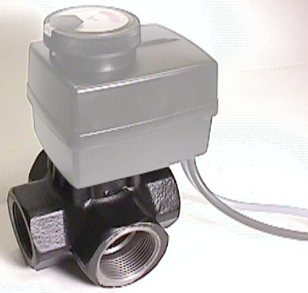
- Can be automated with the M6063 actuator.

SPECIFICATIONS
Important
The specifications given in this publication do not include normal manufacturing tolerances; therefore,an individual unit may not exactly match the listed specifications. Also, this product is tested and calibrated under closely controlled conditions and some minor differences in performance can be expected if those conditions are changed.
Models:
The V5442N provides mixing of both loop supply and boiler return water in hydronic heating systems. They can be automated with an M6063A actuator and a tri-state (floating) controller.
V5442N
Mechanical Specifications:
Fittings: Female NPT threads, 3/4 to 1 1/4″.
Dimensions: see Fig. 1, Table 1. Materials: Cast iron body Double O-rings Chrome-plated interior cast iron parts
Water: maximum 50% glycol solution
NOTE: Cannot be used in open systems such as Combo heating where fresh water is present. Valve will corrode.
Static pressure rating: 90 psi (600 kPa)
Differential pressure rating: 15 psi (100 kPa)
Cv: see Table 1.
Leakage: less than 1% of Cv
Weight: see Table 1.
Temperature Ratings:
Water: 36°F to 230°F (2° to 110°C).
Shipping: -40°F to 140°F (-40° to 60°C)
Humidity Ratings:
Less than 90% RH, non-condensing.
Controller Compatibility:
Must be used with M6063 actuator.
Cross Reference:
V5442N functionally replaces Centra ZRK compact rotary mixing valves and Centra ZR series rotary mixing valves if piping is reconfigured to injection mixing.
Replacement Parts:
P/N 071161035 replacement O-ring.

Table. 1 V5442N specification by valve size.
| Size [i] | [a] | [SW] | [C] | [C] with actuator | Net Weight | Cv |
| 3/4″ | 3 3/8″ (85 mm) |
1 5/8″ (41 mm) | 13 3/8″ (304 mm) | 13 3/4″ (350 mm) |
2.2 lb. (1.0 kg) | 7. |
| 1″ | 12. | |||||
| 1 1/4″ | 4 1/8 (105 mm) |
1 13/16″ (46 mm) | 13 9/16″ (345 mm) | 3.3 lb. (1.5 kg) | 19. |
ORDERING INFORMATION
When purchasing replacement or modernization products from your wholesaler or distributor, refer to the price sheets for complete ordering number.
If you have additional questions, need further information, or would like to comment on our products or services, please write or phone:
- Your local Home and Building Control Sales Office (check white pages of your phone directory.)
- Home and Building Control Customer Logistics
Honeywell Inc. 1885 Douglas Drive North
Minneapolis, Minnesota 55422-4386 (612) 951-1000
In Canada – Honeywell Limited-Honeywell Limitée, 155 Gordon Baker Road, North York, Ontario M2H 3N7.
International Sales and Service Offices in all principal cities of the world. Manufacturing in Australia, Canada, Finland, France,
Germany, Japan, Mexico, Netherlands, Spain, Taiwan, United Kingdom, U.S.A.
INSTALLATION
When Installing this Product . . .
- Read these instructions carefully. Failure to follow them could damage the product or cause a hazardous condition.
- Check the ratings given in the instructions and on the product to make sure the product is suitable for your application.
- The installer must be a trained, experienced service technician.
- After installation is complete, check out product operation as provided in these instructions.
- Follow local codes for installation and application.
Fig: 2 V5442 installations and orientation (Boiler supply from left).

Mounting
Valve
If you intend to control the valve with an outdoor temperature com- pensator, we recommend installing the valve body within 20″ (0.5 m)
of the OTC panel to simplify the wiring.
The valve must be oriented correctly towards the boiler supply water in order to work correctly. Boiler supply water may enter vertically from below, or horizontally from the left, or right of the valve. Mixed loop supply exits the valve horizontally (left or right) with the bottom boiler supply, or from the top with a left-handed or right-handed boiler supply. The position indication scale must not point to the floor.
A. Mount the valve at least 32″ (0.8 m) above the return line to prevent thermal siphoning. See Fig. 2.
Position the valve body so that boiler water enters the port marked by the boss.
See Fig.4 for possible mounting orientations for the V5442, and select the appropriate configuration.
B. Install the valve body in the pipes. Use NPT-to-sweat adapters if installing on the copper pipe. Unions are not required for serviceability but may speed installation.
Note: Threaded fittings must have pipe dope or Teflon™ tape to prevent leakage.
C. Identify the mixed output port, and select the corresponding range on the valve position indicator scale. See Fig. 3.
D. If using the valve manually, clip the stop pin from the molding sprue on the handle and insert the pin in the hole, according to
Fig.3. Assemble the handle onto the valve.
E. For other valve orientations, use the manual handle to align the position indicator on the valve’s square drive socket with the mixed output port. The mixed output will be either be 90° counterclockwise or clockwise relative to the boiler supply input port. Insert the stop pin into the appropriate hole on the handle and assemble the handle to the valve body.
Refer to Fig.5 to 8 for piping options in various hydronic systems.

Fig. 4 Valve and handle the installation for other piping configurations
| A. Boiler supply enters from left, mixed output exits from top. |
B. Boiler supply enters from right, mixed output exits from the top. |
C. Boiler supply enters
from bottom, mixed output exits from left. |
D. Boiler supply enters from bottom, mixed output exits from right. |


SETTINGS
The indicator scale on the V5442 ranges from 1 to 9, where 1 (minimum) corresponds to no flow from boiler to loop and full return of boiler supply to boiler return. This scale is approximately proportional to radiation heat out put, and inversely proportional to boiler return water tem perature, but is not calibrated and intended for reference only.
OPERATION
The rotary control plug of the V5442 diverts boiler supply water to both the loop supply and boiler return. At the same time, the control plug also diverts loop return water to the boiler return and back to the loop supply. When the loop does not use much boiler water, most of it is returned to the boiler. The loop supply water temperature is the result of mixing boiler supply and loop return water, and
boiler return water temperature is the result of mixing loop return water with boiler supply water.
The control plug has a modified equal percentage mixing characteristic on the mixed loop output to give linear heat output in the space. The plug uses a linear mixing characteristic on the mixed boiler return to give linear temperature control of boiler return water.
The V5442 may be used to control space temperature for comfort, boiler return water temperature to prevent boiler shock and ondensation, or both simultaneously, depend ing on the sophistication of the control system.
In low-temperature systems such as radiant floor heating, the V5442 may be used for mixing in an injection configura tion (See Fig. 8). In these configurations, the V5442 has an effective Cv of a much larger valve.

CHECKOUT AND TEST
Checkout
- Turn on loop (and main) circulators. Set the boiler Aquastat control to its operating set point at design conditions.
- Rotate valve handle to 9. Verify that all boiler supply water is being sent to the loop, that is, that the loop sup ply pipe is the same temperature as the boiler supply, and the boiler return pipe is the same temperature as the loop return pipe.
- Rotate valve handle to 1. Verify that all boiler supply water is being sent to the boiler return, that is, that the loop supply pipe is the same temperature as the loop return pipe, and the boiler return pipe is the same tem perature as the boiler supply pipe.
- Rotate the handle to set desired mixed loop tempera Tue. Verify that the boiler return water temperature meets the boiler manufacturers or industry recommen dating. Make a prominent note of the setting for future reference.
Note: If the boiler is fitted with a reset control such a s the AQ475 Aquatrol Outdoor Temperature Compensator, loop temperature will vary proportionately with the boiler supply temperature.
TROUBLESHOOTING
Table 2. Troubleshooting
| Symptom | Possible Causes | Action |
| Space temperature too low. | 1. Thermostat set too low. 2. Mixed supply water not hot enough. |
1. Turn up the thermostat. 2. Set V5442 to a higher number |
| Boiler return temperature too low. | 1. Boiler Aquastat control set too low. 2. Mixed return water not hot enough. 3. Aquatrol minimum temperature too low. |
1. Turn up Aquastat. 2.Set V5442 to lower the number 3. Increase Aquatrol minimum temperature setting |
| Space gets colder as higher valve settings selected | Loop Supply and boiler return pipes are reversed. | Switch control handles to opposite scale. |
SERVICING
The V5442 is designed to give years of trouble-free operation, provided it is used in an oxygen-depleted hydronic heating system. The V5442 may be used in a combo heating system only with heat exchangers between the potable and hydronic heating systems.
Since the V5442 is a gate-type valve, we recommend that the hydronic system be flushed before putting the valve into operation to minimize potential damage to the seals by debris in the system. We also recommend adding Y-strainers and a 10% side-stream filter to the system after flushing to capture debris that may be added in the future through the boiler feed water valve.
In automatic control systems where the V5442 has been motorized with an M6063 actuator, the V5442 should be operated every 3 days or so during the offseason to ensure the valve does not seize up.
If the valve stem starts to leak, replace the O-ring as shown in Fig.9.

V5442N “Corona” 4-way Compact Rotary Mixing Valves — TROUBLESHOOTING • SERVICING
Home and Building Control
Honeywell Inc.
1885 Douglas Drive North
Minneapolis, MN
55422-4386
Honeywell Limited-Honeywell Limitée
155 Gordon Baker Road
MN North
York, ON
M2H 3N7
95C-10888 RJ 10/99
Printed in U.S.A.
Copyright © Honeywell Limited/Limitée • All Rights Reserved