Honeywell Fan Coil Valve Actuators User Guide
Honeywell Fan Coil Valve Actuators User Guide

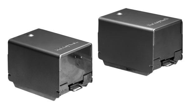

The VU443, VU444, VU843, and VU844 Fan Coil Valve Actuators are used in conjunction with the VU52, VU53, and VU54 fan coil valves for controlling the flow of hot or chilled water. These valves are humidity resistant and are suitable for use in condensing, non-corrosive environments.
SPECIFICATIONS
Actuator Electrical Rating & Connections: 10 VA maximum.

Note: Motors for all the above models are Class A, Plated.
End Switch Rating:
2.2 A inductive from 5 to 110 Vac. 1.0 A inductive above 110 Vic to 277 Vac. Min. DC switching capability: 5 mA @ 24 Vdc.
Maximum Ambient @ Fluid Temperature Rating:
Standard models (with class A motor): 125° F (52° C) ambient @ 200° F (93° C) fluid.
Minimum Ambient Temperature: 34° F (1° C).
Shipping and Storage Temperature: -40° F to 150° F (-40° C to 65° C).
Atmosphere: Non-corrosive, non-explosive, condensing.
Noise Rating: Low noise – non-obtrusive.
Materials:
Case: stainless steel.
Cover: aluminum.
Sector gear: reinforced with
KEVLAR® brand fiber.
KEVLAR® is a Dupont registered trademark.
Approvals: CSA C/US Certified.
Dimensions: See Fig. 1.


INSTALLATION
When Installing this Product…
- Read these instructions carefully. Failure to follow them could damage the product or cause a hazardous condition.
- Check the ratings given in the instructions and on the product to make sure the product is suitable for your application.
- Installer must be a trained, experienced service technician.
- After installation is complete, check out product operation as provided in these instructions.

- Disconnect power supply before connecting wiring to prevent electrical shock of equipment damage.
- On 24V systems, never jumper the valve coil terminals even temporarily. This can burn out the heat anticipator in the thermostat.
To Install and Remove Actuator
INSTALLING ACTUATOR ON VU-SERIES VALVE BODY ASSEMBLY
- Orient slot in shaft of VU-series valve body toward notch in side of body (i.e. 90° to water flow.) See Fig.2. This lifts the ball off seat, prevents damage to the ball seal while soldering, and makes actuator attachment easier.
- Install valve body into pipe.
- Wiring connections may be made either before or after the actuator is installed on the valve body.
- Place manual operating lever on the actuator in the MAN. OPEN position.
- Line up motor coupling to slot in shaft of body and fit the head onto the valve body, ensuring that the shaft seats correctly. (See Fig. 2).
- Snap actuator onto body by pressing down.
- Make wiring connections. Refer to wiring section for proper instructions.
Inspect the actuator installation and the valve body to ensure that all connections and adjustments have been correctly made. Adjust the thermostat or controller connected to the valve so that the valve runs through its cycle. Make sure the valve runs smoothly and positively from closed to open to closed again.

REMOVING ACTUATOR FROM THE VU-SERIES VALVE BODY ASSEMBLY (SEE FIG. 3)
NOTE: It is not necessary to drain the system if the valve body assembly remains in the pipeline.
- Switch power supplies OFF. Disconnect electrical leads, carefully noting the position and color of each lead.
- Place the manual operating lever in the MAN. OPEN position.
- Remove actuator by depressing locking button and lifting straight up.

WIRING
Disconnect the power supply before connecting wiring to prevent electrical shock or equipment damage. All wiring must comply with local codes and ordinances.
TO ATTACH FLEXIBLE CONDUIT
- Strip cable jacket.
- Fit conduit strain relief onto cable.
- Slide strain relief nut over wires.
- Connect cable and actuator wires.
- Slide cable wires down through slot in the wiring hole, so that the strain relief nut is inside the actuator housing.
- Secure nut onto strain relief.
- Install actuator cover.


OPERATION
On 24V systems, never jumper the valve coil terminals even temporarily. This can burn out the heat anticipator in the thermostat.
AUTOMATIC OPERATION
On a call for heat or cool by the fan coil thermostat, the valve motor operates, opening the valve. When the call ends, the valve closes by integral spring return.
MANUAL OPERATION
The 2-way normally closed and 3-way motorized valve actuators can be opened manually by lifting the manual opening lever over the stop and pushing slowly and firmly to the MAN. OPEN position. The stop permits the valve to be locked in the open position. The valve returns to automatic position when it is energized.
NORMALLY CLOSED
With the manual opener set to AUTO and the actuator energized, the A port is opened as shown in Fig. 6A and 7A. When the actuator is de-energized, a spring-return mechanism drives the valve to the port A closed position as shown in Fig. 6B and 7B. The valve can also be opened with no electrical power by moving the manual opening lever over the stop and pushing slowly and firmly to the MAN. OPEN position. The stop permits the valve to be locked in an open position. The valve returns to the automatic position when the valve is energized.
NORMALLY OPEN
With the manual opener set to AUTO and the actuator energized, the A port is closed as shown in Fig. 6B.
NOTE: Inlet and Outlet Ports are indicated by a flow direction arrow on the valve body.


CHECKOUT
SET TO HEATING MODE
- Raise the setpoint on the zone thermostat above the room temperature to initiate a call for heat.
- Observe all control devices – the valve should open.
- Lower the setpoint on the zone thermostat below the room temperature.
- Observe the control devices. The valve should close and the auxiliary equipment should stop.
SET TO COOLING MODE
- Lower the setpoint on the zone thermostat below the room temperature to initiate a call for cooling.
- Observe all control devices – the valve should open.
- Raise the setpoint on the zone thermostat above the room temperature.
- Observe the control devices. The valve should close.
SERVICE
This valve should be serviced by a trained, experienced service technician.
- If the valve is leaking, drain the system and check to see if the O-ring needs replacing.
- If the gear train is damaged, replace the entire actuator. See the Installation section. If the motor is burned out, replace the motor.
- Wear safety glasses to protect eyes from injury when removing or installing the large spring clip that holds the actuator plate to the valve body. Use proper snap ring pliers to remove or install spring clip.
NOTE:
Honeywell fan coil valves are designed and tested for silent operation in properly designed and installed systems; however, water noises can occur as a result of excessive water velocity or piping noises can occur in high temperature (higher than 212° F [100° C]) systems with insufficient water pressure. Valves are designed for normal cycling operations. Product life will be shortened if energized continuously or if operated above rated temperatures.
Use VU443/843 actuators ONLY with VU53 2-way normally close valve bodies. Water hammer may result and actuator life will be shortened if used on VU54 3-way body.
Use VU444/844 actuators on either VU52 2-way normally open bodies or VU54 3-way diverting valve bodies. Close-off pressure ratings will be reduced when used with VU53.
Automation and Control Solutions
Honeywell International Inc.
1985 Douglas Drive North Golden Valley, MN 55422 customer.honeywell.com

® U.S. Registered Trademark
© 2010 Honeywell International Inc.
95C-10883EFS–01 T.D. Rev. 10-10
Printed in U.S.A.