Honeywell Protectorelay Oil Burner Controls User Guide


PROTECTORELAY OIL BURNER CONTROLS
This is a legacy product document supported by Resideo. This product is no longer manufactured.

R4184D;
R8184G,N
THESE INTERMITTENT IGNITION OIL PRIMARY CONTROLS OPERATE THE OIL BURNER, OIL VALVE (IF DESIRED), AND THE IGNITION TRANSFORMER IN RESPONSE TO A CALL FOR HEAT IN OIL BURNER SYSTEMS.
- R4184 and R8184 provide intermittent ignition.
- Used with C554 Cadmium Sulfide Cell.
- R4184 models are used with a 120 Vac thermostat; R8184 models are used with a 24 Vac thermostat.
- Integral transformer on R8184 models powers low voltage control circuit.
- Solid-state flame sensing circuit.
- Enclosed safety switch with external red reset button.
- Safety switch must be manually reset after safety
- R8184G model available with manual trip safety switch lever and lockout indicator light on the terminal strip.
- 15, 30, or 45-second safety switch timing.
- Exposed terminal strip with screw terminals for low voltage connections.
- Color-coded lead wires for line voltage connections.
SPECIFICATIONS
IMPORTANT
THE SPECIFICATIONS GIVEN IN THIS PUBLICATION DO NOT INCLUDE NORMAL MANUFACTURING TOLERANCES. THEREFORE, THIS UNIT MAY NOT MATCH THE LISTED SPECIFICATIONS EXACTLY. ALSO, THIS PRODUCT IS TESTED AND CALIBRATED UNDER CLOSELY CONTROLLED CONDITIONS, AND SOME MINOR DIFFERENCES IN PERFORMANCE CAN BE EXPECTED IF THOSE CONDITIONS ARE CHANGED.
TRADELINE MODELS
TRADELINE models are selected and packaged to provide ease of stocking, ease of handling, and maximum replacement value. Specifications of TRADELINE models are the same as those of standard models except as noted below.
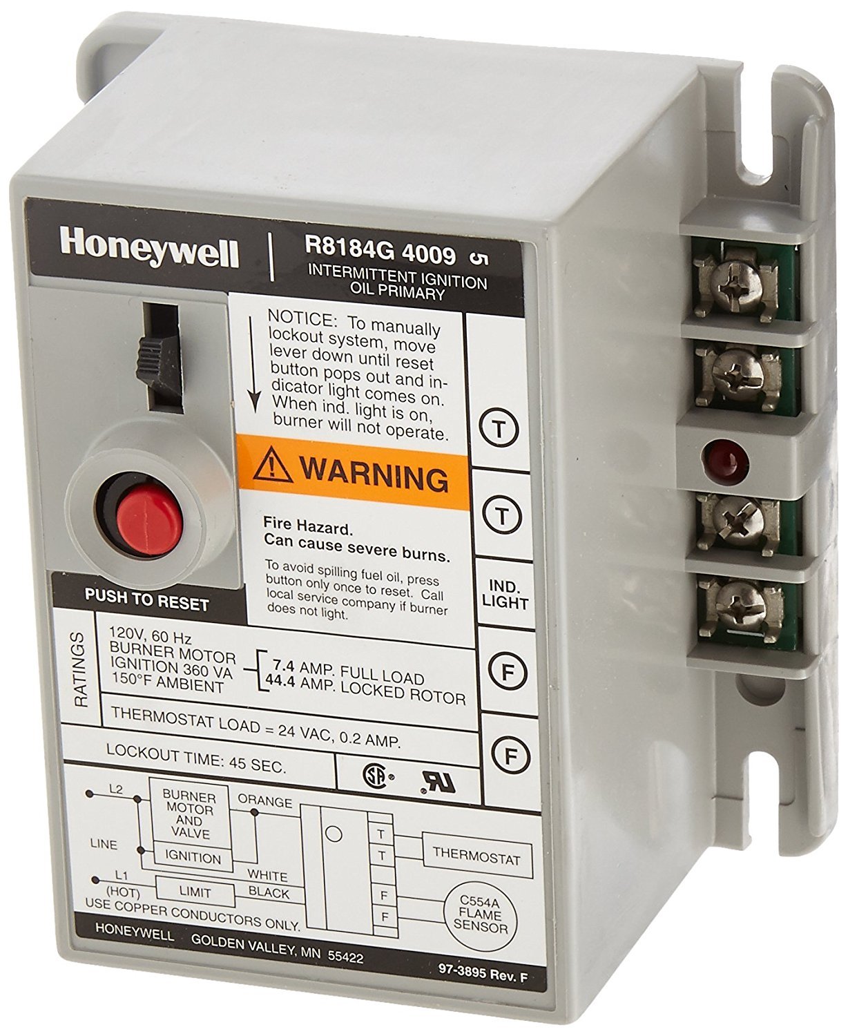
R8184G Protectorelay Oil Primary Control.
ELECTRICAL RATINGS:
Voltage and Frequency-120 Vac, 60 Hz.
Load Relay Contacts (A)—
| 120 Vac | 240 Vac | |
| Full Load | 7.4 | 3.7 |
| Locked Rotor | 44.4 | 22.2 |
Ignition Rating: 360 VA in addition to load relay rating.
SAFETY SWITCH TIMING: 45 seconds.
FEATURES:
- Manual trip safety switch lever.
- Lockout indicator light on the terminal strip.
- TRADELINE package with cross-reference label and special instruction sheet.
- Remote lockout indication capability.
STANDARD MODELS_____________________________
MODELS:
R4184D Protectorelay Oil Primary Control—used with a line voltage thermostat.
R8184G, N Protectorelay Oil Primary Controls—used with low voltage thermostats.
ELECTRICAL RATINGS:
Voltage and Frequency—
R4184D-120 V, 60 Hz.
R8184G-120 V, 60 Hz; 220/240 V, 50/60 Hz.
R8184N-120V, 60 Hz.
Load Relay Contacts (A)—
| MODEL | 120 Vac | 240 Vac | ||
| FL | LR | FL | LR | |
| R4184D, R8184G.N (45-second models) | 7.4 | 44.4 | 3.7 | 22.2 |
| R8184G(15, 30-second models) | 10.0 | 60.0 | 5.0 | 30.0 |
Ignition Rating (in addition to bad relay racing)— R41840, R8184G, N (45-second models): 360 VA. R8184G (15, 30-second models): 500 VA. Maximum Watts (at 60 Hz)—Start: 8.2 A, Running: 5.5 A.
ORDERING INFORMATION
WHEN PURCHASING REPLACEMENT AND MODERNIZATION PRODUCTS FROM YOUR TRADELINE WHOLESALER OR YOUR DISTRIBUTOR, REFER TO THE TRADELINE CATALOG OR PRICE SHEETS FOR COMPLETE ORDERING NUMBER, OR SPECIFY-
- Order number, Tradeline if desired.
- Voltage and frequency.
- Safety switch timing.
- Thermostat heat anticipator setting.
- Manual trip safety switch, if desired.
- Lockout indicator light, if desired.
- Remote lockout indication capability, if desired.
IF YOU HAVE ADDITIONAL QUESTIONS, NEED FURTHER INFORMATION, OR WOULD LIKE TO COMMENT ON OUR PRODUCTS OR SERVICES, PLEASE WRITE OR PHONE:
- YOUR LOCAL HONEYWELL RESIDENTIAL AND BUILDING CONTROLS DIVISION SALES OFFICE (CHECK WHITE PAGES OF YOUR PHONE DIRECTORY).
- RESIDENTIAL AND BUILDING CONTROLS DIVISION CUSTOMER SATISFACTION HONEYWELL INC., 1885 DOUGLAS DRIVE NORTH MINNEAPOLIS, MINNESOTA 55422 (612) 542-7500
(IN CANADA—HONEYWELL LIMITED, 740 ELLESMERE ROAD, SCARBOROUGH, ONTARIO M1 P 2V9) INTERNATIONAL SALES AND SERVICE OFFICES IN ALL PRINCIPAL CITIES OF THE WORLD.
SAFETY SWITCH TIMING:
R4184D, R8184N-45 seconds.
R8184G-15, 30 or 45 seconds.
IGNITION SEQUENCE: All models provide intermittent ignition—ignition is on whenever the burner is on.
THERMOSTAT HEAT ANTICIPATOR SETTING: R8184G-0.2 A or 0.4 A, depending on model; R4184D, R8184N-0.2 A.
AMBIENT TEMPERATURE RANGE: -40° F to 130° F (-40° C to 54° CI.
Models also available with -40° F to 150° F [-40° C to 66° Cl
MOUNTING: Mount on a standard 4 x 4 in. junction box; some R4184D and R8184G, N models mount directly on the burner.
R8184G1427 must be mounted with the device label facing upward. Refer to Fig. 4.
DIMENSIONS: See Figs. 1 and 2.
ACCESSORY: Part No. 128732 Terminal Cover (see Fig. 3).
MANUAL TRIP SAFETY SWITCH LEVER: TRADELINE models include a lever to manually trip the safety switch.
LOCKOUT INDICATION: TRADELINE R8184G includes a light-emitting diode (LED) on the terminal strip that lights to indicate when the oil primary control has locked out on safety.
FLAME DETECTOR (order separately): C554A Cadmium Sulfide Cell.
UNDERWRITERS LABORATORIES INC. COMPONENT RECOGNIZED: File No. MP268, Vol. 9, Guide No. MCCZ2.
CANADIAN STANDARDS ASSOCIATION LISTED: File No. LR1620, Guide No. 2642-01.

FIG. 1- APPROXIMATE MOUNTING DIMENSION IN INCHES AND [MILLIMETERS] (R8184G shown).

FIG. 2- BACK OF OIL PRIMARY CONTROL SHOWING LEADER CHANNELS.
INSTALLATION
WHEN INSTALLING THIS PRODUCT…
- Read these instructions carefully. Failure to follow them could damage the product or cause a hazardous
- Check the ratings given in the instructions and on the product to make sure the product is suitable for your
- The installer must be a trained, experienced service tech
- After installation is complete, check out product operation as provided in these instructions.
CAUTION
|
CHOOSE LOCATION
This unit can be mounted on a 4 x 4 in. junction box, directly on the burner housing or inside the appliance cabinet. In a replacement application, mount in the same location as the old control. Line voltage connections must be in a wiring enclosure, such as a junction box or the appliance wiring compartment.
Make sure operating temperatures at the selected location will be within the ambient temperature range listed in SPECIFICATIONS.
MAKE WIRING CONNECTIONS AND MOUNT CONTROL
Wiring must comply with all local codes and ordinances.
Before mounting the oil primary control, make the line voltage connections as shown in Figs. 5 through 8. Splice leads with solderless connectors. Do not exceed load ratings shown on the device label or in the Specifications section, page 2.
If cad cell leads are run with line voltage wires, break out knockout, if necessary (models available with knockout already removed), at the bottom of the low voltage terminal strip and thread cad cell leads through the hole.
If necessary, use control as a template to mark and drill new mounting holes. Mount using No. 6 screws (obtain locally).
After mounting, make low voltage connections to the screw terminals. Strip leads 3/8 in. [10 mm) and insert under the terminal screw. See Fig. 3 or 4. For R8184G, connect cad cell leads to F-F terminals and thermostat leads to T-T terminals. Refer to Fig. 6. For R8184N, connect cad cell leads to F1-F2 terminals, thermostat leads to T1-T2 terminals and heater to T2-F2 terminals. Refer to Fig. 8.

FIG.3 – MOUNTING COUNTING CONTROL WITH 130º F [59º C ] MAXIMUM AMBIENT TEMPERATIRE.

FIG.4 – MOUNTING THE R818G1427.

FIG.5- TYPICAL HOOKUP FOR R4184D.

FIG. 6 – TYPICAL HOOKUP FOR R8184G WITHOUT REMOTE ALARM.

FIG. 7 – TYPICAL HOOKUP FOR R8184G WITH REMOTE ALARM AND LOCKOUT LED.

FIG. 8 – TYPICAL HOOKUP FOR R8184N.
OPERATION
| EXTERNAL ACTION | OIL PRIMARY ACTION |
| Connect line voltage power. | R4184—No action unless line voltage thermostat and limit contacts are closed. Then same as “Thermostat calls for heat.” R8184—Transformer primary is energized if limit contacts are closed. |
| The thermostat calls for heat. | R4184—Primary is energized. R4184, R8184—Relay 1K pulls in, closing contact 1K2, energizing the burner motor, oil valve, and ignition. Contact 1 K1 also closes, but the safety switch heater continues to heat through the electronic network. |
| Cad cell senses flame. | The safety switch heater is de-energized. Burner operation continues under the control of the thermostat and limit. |
| Heat demand satisfied. | R4184—Primary is de-energized, opening relay 1K and shutting off the burner motor, oil valve, and ignition. R8184—Relay 1K is de-energized, shutting off the burner motor, oil valve, and ignition. |
| Burner fails to ignite on call for heat. | The safety switch is heated through the electronic network and opens in approximately 15, 30, or 45 seconds, depending on the model. Indicator light, if provided, comes on. Relay 1K is de-energized, opening contacts 1 K2 and shutting off the burner motor, oil valve, and ignition. Requires manual resetting of the safety switch. Allow at least 5 minutes for the switch to cool. |
| Flame fails during the burner-on cycle. | When cad cell senses no flame, the safety switch heater begins heating through the electronic network. After approximately 15, 30, or 45 seconds (depending on model), the safety switch opens, de-energizing relay 1K. Indicator light, if provided, comes on. Contacts 1 K2 open, shutting off the burner motor, oil valve, and ignition. The safety switch must be manually reset to restart the burner. If the flame is re-established within the safety switch heating period, the operation returns to normal. |
| Power failure during the call for heat. | The burner shuts down safely and automatically returns to normal operation when power is restored. |
CAUTION
The heating system shuts down when the oil primary locks out on safety. Freezeout (i.e. cold house, frozen pipes) can occur if weather conditions are severe. To avoid freezeout, models are available with lockout light mounted on the unit or mounted remotely on a thermostat subbase. An isolated alarm relay can also be mounted in the living area.
CHECKOUT
START SYSTEM
WARNING
Fire hazard.
Can cause severe burns.
Make sure the combustion chamber Is free of oil or oil vapor before starting the system.
- Open hand valve in the oil supply line.
- Make sure the system is powered. Check circuit breaker or fuse and close system switch, if provided.
- Push in and release the red reset button.
- Set the thermostat to call for heat.
- The burner should light and operate until the call for heat ends.
CHECK SAFETY FEATURES
Simulate flame failure:
- Follow staffing procedure to turn on the burner.
- Close hand valve in the oil supply line.
- Safety switch should lockout in safety switch timing indicated on the label. Indicator light, if provided, should come on. Ignition and motor should stop and the oil valve should close.
Simulate ignition failure:
- Follow starting procedure to turn on the burner, except do not open oil supply hand valve.
- Safety switch should lockout in safety switch timing (see label). Indicator light, if provided, should come on. Ignition and motor should stop and the oil valve should close. If the system does not operate as described, proceed to Troubleshoot.
TROUBLESHOOTING AND MAINTENACE
IMPORTANT
This control contains no field-serviceable parts. Do not attempt to take it apart. Replace the entire control if the operation is not as described.
To completely troubleshoot an oil burner installation, check the burner, ignition transformer, oil primary control, and cad cell for proper operation and condition. Light-emitting diode (LED), if provided, on oil primary lights to indicate the system has locked out on safety.
PRELIMINARY STEPS Before checking the oil primary and cad cell, make these preliminary checks. Repair or replace as indicated.
- Wiring connections, power supply, and burner motor fuse. Make sure power is on to the controls, burner motor, and ignition transformer.
- Limit switch.
- Ignition transformer.
- Electrode gap and position.
- Contacts between ignition transformer and electrode. 6.011 pump pressure.
- Oil piping to tank.
- Oil nozzle.
- Oii supply.
- Oil filter. If the system is still not operating properly, check the cad cell and oil primary control as instructed below.
CHECK CAD CELL AND OIL PRIMARY CONTROL
CAUTION
Since troubleshooting is done with the system powered, observe all necessary precautions to prevent electrical shock or equipment damage.
You’ll need the following equipment to check the oil primary and cad cell.
- Screwdriver
- 0-150 Vac voltmeter
- Insulated jumper wires with both ends stripped
- Ohmmeter
- 2700 ohm resistor (optional)
Burner Motor Does Not Start When Thermostat Calls For Heat
PRELIMINARY CHECKS
- Make sure the limit switch is closed.
- Check for line voltage power at the coil primary. With the thermostat calling for heat, the voltage between black and white lead wires on oil primary should be 120 Vac (or 220/240 Vac, depending on the model).
| PROCEDURE | CORRECTIVE ACTION | |
| BURNER STARTS | BURNER DOESN’T START | |
| 1. Jumper thermostat terminals– Low volt thermostat—at oil primary. — Line volt thermostat—at the thermostat.
|
The trouble is in the thermostat circuit. Check thermostat and wiring connections.
|
Trouble is in cad cell or oil primary. Go to step 2. |
| 2. Disconnect 1 cad cell lead. | Cad cell is seeing external light. is defective, or cad cell connections are shorted. Go to step 3. | Disconnect power; check all wiring connections. Tighten any loose connections, if necessary, and retest. If the burner motor and ignition still don’t start, replace the oil primarily. If the ignition is on and the burner motor is off, check the burner motor and wiring connections to the motor. Replace burner motor, if necessary. |
| 3. Turn off the burner and reconnect the cad cell. Make sure F-F or F1-F, terminals are not shorted. Shield cad cell from external light, and jumper T-T or Ti-T2 terminals to start the burner. | Eliminate external light source or permanently shield cad cell. | Replace cad cell with Part No. 130367. |
Burner Motor Starts But
Flame Is Not Established Check burner and ignition transformer per manufacturer’s recommendations. This is not an oil primary or cad cell problem.
Burner Starts, Flame Is Established; Then Burner Locks Out On Safety
| PROCEDURE | CORRECTIVE ACTION | |
| BURNER LOCKS OUT | BURNER KEEPS RUNNING | |
| 1. a. Reset the safety switch by pushing the red reset button. b. Disconnect cad cell lead wires at oil primary. c. Jumper thermostat terminals to start burner— Low volt thermostat— at oil primary. — Line volt thermostat—at the thermostat. d. Atter flame is established, but before safety switch locks out, short cad cell by jumpering F-F or Fi-F2 terminals. |
Oil primary control is a detective—replace. If there is any doubt that F-F or F,-F2terminals have jumpered within safety switch timing, wait 5 minutes, then repeat procedure (steps la-1d). | Check cad cell with an ohmmeter, see Cad Cell Troubleshooting table on page 10. If ohmmeter is not available, go to step 2. |
| 2. a. Disconnect line voltage power and reconnect cad cell F-F or Fi-F2 terminals. b. Unplug cad cell and clean face with a soft cloth. Check to sight for a clear view of the flame. Replace cell in the socket. c. Reconnect line voltage power. Reset safety switch by pushing the red reset button, and jumper thermostat terminals to start burner- – Low volt thermostat—at oil primary. — Line volt thermostat—at the thermostat. |
Replace cad cell with Part No. 130367, go to step 3. | Cad cell is okay. |
| 3. Reset the safety switch and restart the burner. | Check cad cell view of the flame, flame shape, and oil nozzle. If the flame is normal and cad cell has a good view of the flame, check for open circuits in socket assembly wiring. Replace assembly, if necessary.a | Cad cell and socket assembly are okay. |
If cad cell is okay and oil primary appears okay but the system continues to lock out on safety, repeat steps la-1d using a 2700 ohm resistor to jumper F-F or F1-F2terminals. The burner will lock out if oil primary is defective; replace oil primarily, if necessary.
CAD CELL TROUBLESHOOTING
Check cad cell by reading resistance with ohmmeter while the flame is present. See the table below for cause and corrective action to be taken for resistance that is read.
| OHMMETER READING | CAUSE | ACTION |
| 0 ohms. | Short circuit. | Check for pinched cad cell lead wires. |
| Less than 1600 ohms, but not 0. | Cad cell and application are operating correctly. | Recheck oil primary using a 2700 ohm resistor to jumper F-F or F,-F2terminals; repeat steps 1 a-1d under “Burner Starts, Flame is Established” on page 9. |
| Over 1600 ohms, but not infinite. |
|
|
| Infinite resistance. | Open circuit | Check for improper wiring, loose cad cell in the holder, or defective cad cell. Replace defective cad cell with Part No. 130367. |
TRIP SAFETY SWITCH BEFORE OPERATING BURNER MAINTENANCE (Tradeline model only)
CAUTION
Tripping the safety switch shuts down the burner but does not disconnect the power supply. Turn off power at the system switch or circuit breaker before servicing the control system, burner motor, oil valve, or ignition to avoid electrical shock.
To trip the safety switch, move the safety switch lever down until the red reset button pops out and the indicator light comes on. See Fig. 9. The burner will not operate until the safety switch is reset by pushing in the red reset button.

FIG. 9 – MOVFE LEVER DOWN TO TRIP SAFETY SWITCH
Honeywell Inc.
U.S.A.: 1885 Douglas Drive N.|
Golden Valley, MN 55422-4386
CANADA: 740 Ellesmere Road Scarborough, Ontario M1 P 2V9
International Sales Offices in all principal cities of the world. Manufacturing in Australia, Canada, Finland, France, Germany, Japan, Mexico, Netherlands, Spain, Taiwan. United Kingdom, U.S.A.
PRINTED IN U.S.A.
