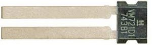
Honeywell AMR 2-Pin PWM Speed and Direction Sensor Integrated Circuit VM721D1 Installation Guide
Honeywell AMR 2-Pin PWM Speed and Direction Sensor Integrated Circuit VM721D1 Installation Guide

GENERAL INFORMATION
Honeywell’s Anisotropic Magnetoresistive (AMR) 2-Pin Pulse Width Modulated (PWM) Speed and Direction Sensor Integrated Circuit (IC) is designed to detect the speed and direction of a ring magnet encoder target using a unique* bridge design.
The frequency of the digital supply current is proportional to the rotational speed of the target, and the rotational direction is encoded by modulating the pulse width of the supply current.
The sensor IC works over a wide range of speeds, temperatures and air gaps.
- Patent Pending
CAUTION
ELECTROSTATIC DISCHARGE DAMAGE
- Ensure proper ESD precautions are followed when handling this product.
- Failure to comply with these instructions may result in product damage.
CAUTION
ELECTROSTATIC SENSITIVE DEVICES DO NOT OPEN OR HANDLE EXCEPT AT A STATIC FREE WORKSTATION
SOLDERING AND ASSEMBLY
CAUTION
IMPROPER SOLDERING
- Ensure leads are adequately supported during any forming/shearing operation so that they are not stressed inside the plastic case.
- Limit exposure to high temperatures.
Failure to comply with these instructions may result in product damage
Wave solder at 250°C to 260°C [482°F to 500°F] for a maximum of three seconds. Burrs are allowed only if full lead length will pass through a 0,68 mm [0.027 in] dia. hole.
CLEANING
CAUTION
IMPROPER CLEANING
- Do not use pressure wash. High-pressure stream could force contaminants into the package.
Failure to comply with these instructions may result in product damage.
- Use agitated rinse to clean the sensor.
Table 1. Operating Characteristics (Over entire supply voltage range at -40°C ≤ TA ≤ 150°C, unless otherwise specified)
| Characteristic | Symbol | Condition | Min. | Typ. | Max. | Unit |
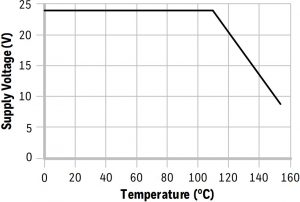
| Supply voltage | VS | -40°C to 110°C | 4.0 | — | 24 | V |
| 150°C | 4.0 | — | 9.0 | |||
| Supply current: | ||||||
| high | ISh | digital high state | 12 | 14 | 16 | mA |
| low | ISl | digital low state | 5.9 | 6.95 | 8.0 | |
| Current ratio | — | — | 1.9 | — | — | — |
| Pulse length: | ton | ms | ||||
| forward | tfwd | — | 38 | 45 | 52 | |
| reverse | trev | — | 76 | 90 | 104 | |
| Output switching time: | ms | |||||
| rise time | tr | metering resistor, no bypass capacitor | — | — | 8 | |
| fall time | tf | metering resistor, no bypass capacitor | — | — | 8 | |
| Switching frequency: | ||||||
| forward | ffwd | limited by length of forward pulse | — | — | 14 | kHz |
| reverse | frev | limited by length of reverse pulse | — | — | 8 |
Table 2. Output Configuration
| Characteristic | Condition | Configuration |
| Number of pulses per pole | — | 1 |
| Forward definition | rotation from pin 2 to pin 1 as shown in Figure 5 | ring magnet rotating from pin 2 to pin 1 (CCW) |
Table 3. Application Requirements (At 4.0 V ≤ VS ≤ 24 V, -40°C ≤ TA ≤ 150°C)
| Characteristic | Symbol | Condition | Min. | Typ. | Max. | Unit |
| Magnetic flux | B | Dmax, max. air gap, max. temp. | ±30 | — | — | Gauss |
| Magnetic flux with valid direction indication, increased jitter |
B |
Dmax, max. air gap, max. temp. |
±10 |
— |
— |
Gauss |
| Metering resistor | R | — | 10 | 100 to 300 | — | Ohm |
Table 4. Absolute Maximum Ratings
| Characteristic | Symbol | Condition | Min. | Typ. | Max. | Unit |
| Operating temperature | Ta | — | -40 [-40] | — | 150 [302] | °C [°F] |
| Junction temperature | TJ | — | -40 [-40] | — | 165 [329] | °C [°F] |
| Storage temperature | TS | — | -40 [-40] | — | 150 [302] | °C [°F] |
| Thermal resistance | RqJA | — | — | — | — | °C/W |
| Supply voltage | VS | — | -26.5 | — | 26.5 | V |
| Soldering temperature | — | 3 s max. | — | — | 260 [500] | °C [°F] |
| ESD (HBM) | VESD | JEDEC JS-002-2014 | — | — | ±6 | kV |
NOTICE
Absolute maximum ratings are the extreme limits the device will momentarily withstand without damage to the device.
Electrical and mechanical characteristics are not guaranteed if the rated voltage and/or currents are exceeded, nor will the device necessarily operate at absolute maximum ratings.
Large, stray magnetic fields in the vicinity of the sensor may adversely affect sensor performance.
Maximum Supply Voltage Rating
Figure 1. Maximum Supply Voltage Rating

Block Diagram
Figure 2. Block Diagram

Figure 3. Basic Application Circuit

Figure 4. Rise and Fall Time Definition

- tr = 10% to 90% rise time
- tf = 90% to 10% fall time
Figure 5. Transfer Characteristics

Sensor IC Mounting Orientation
Figure 6. Sensor IC Mounting Orientation
- Radial
- Axial


Dimensions and Product Marking
Figure 7. Dimensions and Product Marking (For reference only mm/[in])
- Dimensions
- Product Marking
- Sensing Element Edge Distance


RISK TO LIFE OR PROPERTY

Never use this product for an application involving serious risk to life or property without ensuring that the system as a whole has been designed to address the risks, and that this product is properly rated and installed for the intended use within the overall system.
Failure to comply with these instructions could result in death or serious injury.
Warranty/Remedy
Honeywell warrants goods of its manufacture as being free of defective materials and faulty workmanship during the applicable warranty period. Honeywell’s standard product warranty applies unless agreed to otherwise by Honeywell in writing; please refer to your order acknowledgement or consult your local sales office for specific warranty details. If warranted goods are returned to Honeywell during the period of coverage, Honeywell will repair or replace, at its option, without charge those items that Honeywell, in its sole discretion, finds defective.
The foregoing is buyer’s sole remedy and is in lieu of all other warranties, expressed or implied, including those of merchant ability and fitness for a particular purpose. In no event shall Honeywell be liable for consequential, special, or indirect damages .
While Honeywell may provide application assistance personally, through our literature and the Honeywell web site, it is buyer’ssole responsibility to determine the suitability of the product in the application.
Specifications may change without notice. The information we supply is believed to be accurate and reliable as of this writing. However, Honeywell assumes no responsibility for its use.
For more information
Honeywell Advanced Sensing Technologies services its customers through a worldwide network of sales offices and distributors.
For application assistance, current specifications, pricing or the nearest Authorized Distributor, visit sps.honeywell.com/ast or call:
Asia Pacific +65 6355-2828
Europe +44 (0) 1698 481481
USA/Canada +1-800-537-6945
