Honeywell CTP Series Current Transmitters Installation Guide
Honeywell CTP Series Current Transmitters Installation Guide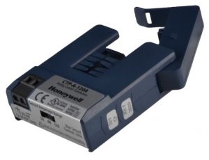

INSTALLATION INSTRUCTIONS
WARNING
This product can expose you to chemicals including 1,3 Butadiene, which is known to the State of California to cause cancer and reproductive harm. For more information, go to www.P65Warnings.ca.gov
DESCRIPTION
The CTP current transmitters monitor the current flow for various electrical equipment. Measured current level is converted into a linear and proportional 0 – 5/10 Vdc or 4- 20mA output signal, which can be monitored by a Building Management, DDC, or PLC controller. Current sensors with switch selectable current ranges provide optimal resolution for greater measuring accuracy.
These current sensors should be used in load trending (current monitoring) type applications.
The split core design make installations easy since no wires need to be disconnected during the installation process.
May be mounted on the conduction (codes permitting) or fix mounted flexibility including DIN rail compatibility.
WARNING
Failure to follow these instructions will result in death or serious injury.
WARNING
- Follow ALL requirements in NFPA 70E for safe work practices and for Personal Protective Equipment (USA) and other applicable local codes when installing this product
- Only qualified electrical personnel should install this product
- Read, understand, and follow all instructions thoroughly
- Install only on insulated conductors
- Lock out and tag out all power sources prior to installation. Use properly rated voltage sensing instrument to determine no voltage is present
WARNING
Automated equipment may start without warning
- Equipment monitored/operated by this device may start without warning. Keep clear of apparatus at all times
IMPORTANT
- Only qualified trade installers should install this product
- This product is not intended for life-safety applications
- Do not install in hazardous or classified locations
- The installer is responsible for all applicable codes
- This product must be installed in a suitable electrical enclosure
- Clamp sensor around INSULATED CONDUCTOR ONLY, 600VAC MAX to be monitored.
INSTALLATION
Disconnect, lock out and tag out all power supplies during installation
- Determine mounting location for the sensor near the conductor to be monitored. The sensor should be located AT LEAST 1/2” from any uninsulated conductor.
- Sensor features a flexible iris which allows the senso r to hang on the conductor if local codes permit. A bracket is included for screw mounting or attaching to DIN rail. For screw mounting, drill two 3/32” pilot holes using the bracket as a template; ensure no drill shavings are present in enclosure. Attach bracket with screws provided.
- Clamp sensor around INSULATED CONDUCTOR ONLY, 600VAC MAX to be monitored.
- Snap the sensor into the mounting bracket.
- Wire the output of the sensor to a control panel analog input. Sensor is self-powered. 12 to 30vdc excitation is required for 4-20mA output models (CTP-A20A and CTP-A-120A). Tighten terminals to 3.5 inlb.
SETUP
Sensors are factory calibrated to three ranges. CTP10V-200A is calibrated to 200A full-scale. No field calibration is required.
2. Move selector switch to desired factory calibrated range setting. Selected range should be greater than the maximum motor current.
Wiring CTP-5V, CTP-10V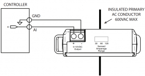

Product Application Limitation:
Honeywell products are not designed for life or safety applications. Honeywell products are not intended for use in critical applications such as nuclear facilities, human implantable device or life support. Honeywell is not liable, in whole or in part, for any claims or damages arising from such uses.
Wiring CTP-A

TECH TIPS
On low current loads, wrap sensor multiple times to increase sensitivity
CAUTION
Do not exceed sensor maximum current. The current detected by the sensor will increase 1X with each wrap.

To monitor loads greater than the current sensor maximum rating
Use a properly rated 5A CT as shown below

CAUTION
5A CT’s can present hazardous voltages. Install CT’s in accordance with manufacturers instructions. Terminate the CT secondary wiring before energizing primary conductor. Remember to consider the ratio of the CT secondary to the sensor full-scale range to determine sensor output. Example: A 300:5A CT will produce 5 amps max, which is 1/6th of the 30 amp full-scale range of the CTP-A-120A. Applying this ratio (1/6) to the 16mA output range (20mA – 4mA) gives a 2.67mA signal change for a reading of 6.67mA at 300 A.
Troubleshooting
| Symptom | Cause | Remedy |
| Sensor output is over maximum output range (5V, 10V, 20 mA) | Amperage is above selected maximum range | See Tech Tip for monitoring loads greater than current sensor maximum rating |
| No output or wrong output voltage | Wiring error | Check polarity Check ground connection |
| Incorrect scaling | Verify controller scaling | |
| No output current | No excitation voltage Backward wiring | Check excitation voltage Check polarity |
| Wrong output current | Incorrect scaling | Verify controller scaling |
RECYCLING
Product should not be thrown away in regular trash. Instead, it should be recycled according to local municipality
OPERATION

Analog current sensors output signal proportional to monitored current.
Typical load status applications include:
- Load trending
- Monitoring process motors and pumps
- Electric heater current monitoring
Specification by Product
| Product Number | Output Type | Range(s) | Max Current |
| CTP-A-20A | Loop-powered 4-20 mA | 5/10/20 A | 200 A |
| CTP-A-120A | Loop-powered 4-20 mA | 30/60/120 A | 200 A |
| CTP-5V-20A | Self-powered 0-5 VDC | 5/10/20 A | 100 A |
| CTP-10V-120A | Self-powered 0-10 VDC | 30/60/120 A | 200 A |
| CTP-10V-200A | Self-powered 0-10 VDC | Fixed, 200 A | 200 A |
| Specification | Rating |
| Accuracy | +/-2% F.S. over 10 to 100% range |
| Ambient Temperature Rating | -15~60 ° C |
| Insulation Class | 600V RMS. For use on insulated conductors only! Use minimum 75 ° C insulated conductor |
| Sensor Power | Induced, 12 to 30 VDC max for loop powered sensors |
| Frequency Range | 50/60Hz |
| Dimensions ( L x W x H) | 2.94” x 2.23” x 0.82” (1.4” H with optional relay module) |
| Sensor Aperture | 0.75” |
| Environmental | Pollution Degree 2 (non-conductive/non- condensing) |
3PZS E516382
RoHS Compliant


Honeywell Building Technologies
In the U.S.: Honeywell 715 Peachtree Street NE Atlanta, GA 30308 customer.honeywell.com
® U.S. Registered Trademark
©2020 Honeywell International Inc. 31-00430—01 M.S. 09-20 Printed in United State
