Honeywell Braukmann Q390 Thermocouples User Guide


Honeywell Braukmann Q390 Thermocouples
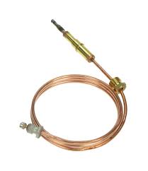

The Honeywell Braukmann Q390 Thermocouples generate a thermoelectric current that senses a pilot flame on gas-fired heating systems. The pilot flame heats the tip of the thermocouple, producing a temperature differential between it and the base. This temperature difference generates a small amount of de power, measured in millivolts.
- Easy pilot burner installation:
- Push-in clip
- Split nut
- Adapter assembly
- Spade or quick-connect terminals available for millivolt gas control connections.
- Male nut connector for Pilotstat safety control power units.
- Available in a variety oflead lengths.
- Q390A Thermocouples include ten units packed in one bag assembly with five push-in clips and five universal adapters, or a box of ten units individually packed with a push-in clip and universal adapter.
Specifications
MODELS:
Q390A Thennocouple
LEAD LENGTHS (Fig. 1):
18, 24, 30 and 36 in. [457,610, 762 and 914 mm].
MILLIVOLTAGE OUIPUTS:
Nonnal Open Circuit Output Range–26 to 32 m V. Lowest Acceptable Open Circuit Output-18 m V. Turndown Open Circuit–2 m V.
- Use Honeywell W129A Millivoltmeter to deternine millivoltage output.
- MAXIMUM DC COLD RESISTANCES AT 80° F [27° C] AMBIENT IB\1PERATURE: 0.02 ohm. (Use Honeywell Wl29A Millivoltmeter to detennine maximum resistance.)
HOT AND COLD JUNCTION TEMPERATURE RATINGS:
HotJunction-1400° F [760° C].
Cold Junction-780° F [416° CJ.
PILOT BURNER USAGE: The Q390 with adapter is compatible with the following Honeywell pilot burners: Q303, Q305, Q308, Q314, Q324 and Q327.

ORDERING INFORMATION
When purchasing replacement and modernization products, specify the complete model number. If you have additional questions, need further information, or want to comment on our products or services, please write or phone:
- Call (612) 542-6577 for the phone number of your local Honeywell Braukmann manufacturer representative.
- To place an order, contact:
Honeywell Braukmann Customer Service
1985 Douglas Drive North
Minneapolis, Minnesota 55422-3992
(612) 542-7106 (Eastern US)
(612)542-7103 (Western US) - Or fax your order to 1-800-356-0149.
THERMOCOUPLES:
Description
Includes ten thermocouples packed in one bag assembly with five push-in clips and five universal adapters; 30 millivolt output. Includes a box of ten thermocouples individually packed with a push-in clip and a universal adapter; 30 millivolt output.
Installation
WHEN INSTALLING THIS PRODUCT …
- Read these instructions carefully. Failure to follow instructions can damage product or cause a hazardous condition.
- Check ratings given in instructions and on product to make sure product is suitable for your application.
- Make sure installer is a trained, experienced service technician.
- After completing installation, use these instructions to check out product operation.
WARNING
FIRE OR EXPLOSION HAZARD CAN CAUSE PROPERTY DAMAGE, SEVERE INJURY, OR DEATH
Follow these warnings exactly:
- Disconnect power supply before wiring to prevent electrical shock or equipment damage.
- To avoid dangerous accumulation of fuel gas, turn off gas supply at appliance service valve before starting installation.
Follow appliance manufacturer’s instructions if available; otherwise, use instructions provided below a<; a guide.
PUSH-IN CLIP DESIGN
- Insert thermocouple tip into hole or barrel provided beneath the pilot burner. Refer to Fig. 2.
- Push in firmly until locked into place.

SPLIT NUT DESIGN
- Remove push-in clip and discard.
- Attach adapter fitting over thermocouple.
- Insert thermocouple tip into hole or barrel provided beneath the piles burner. Refer to fig.3
- Engage attachment nut threads and tighten.

PILOTSTAT SAFETY CONTROL COl\’NECTION
IMPORTANT: This is an electrical connection. Make sure that all connections are clean and tight for proper operation.
- Insert end of lead into female connector on the Pilotstat power unit. Refer to Fig. 4.
- Engage male nut and tum until finger tight.
- Using a wrench, tighten 1/4 tum beyond finger tight.

Start-up and Checkout
ADJUST PILOT FLAME
The pilot flame should envelop 3/8 to 1/2 in. [10 to 13 mm] of the thermocouple tip. Refer to Fig. 5. To adjust pilot flame:
- Remove pilot adjustment cover screw.
- Tum inner pilot adjustment screw clockwise r-\ to decrease or counterclockwise r’\ to increase pilot flame.
- Always replace pilot adjustment cover screw and tighten firmly after completing adjustment to ensure proper operation.
CHECK SAFETY SHUTDOWN PERFORMANCE
- Follow appliance manufacturer’s instructions for lighting pilot and main burner.
- Make sure gas control (if used) opens properly when the pilot is burning normally.
- Extinguish pilot flame. Make sure that pilot gas flow stops within 2-1/2 minutes. Safety shutoff of pilot gas proves complete shutdown because safety shutoff valve blocks flow of gas to main burner and pilot.
- Relight pilot burner using manufacturer’s instructions.
CHECK SYSTEM OPERATION
Set thermostat to call for heat and observe appliance through one complete cycle to make sure it operates properly.

Service
WARNING: FIRE OR EXPLOSION HAZARD CAN CAUSE PROPERTY DAMAGE, SEVERE INJURY, OR DEA TH Perform Gas Leak Test anytime work is done to the system.
THERMOCOUPLE PERFORMANCE
Thermocouples require proper temperature differential between the hot-junction (tip) and cold-junction (base) to provide satisfactory operation of millivoltage gas controls. Thermocouples perform less effectively when exposed to excessive cold-junction or hot-junction temperatures. Excessive hot-junction temperatures can be eliminated by proper pilot flame adjustment. To adjust pilot flame, refer to Start-up and Checkout above. Excessive cold-junction temperatures can be caused by heat radiation from adjacent surfaces or high ambient air temperatures. Excessive cold-junction temperatures can be eliminated by shielding the pilot flame, refer to Fig. 6, or constructing a baffle to direct secondary air over the pilot burner base.
EFFECTIVE IGMTION TEST
The Effective Ignition Test assures that the pilot flame ignites the main burner within four seconds after the gas reaches the main burner. In this test, the pilot flame is just sufficient enough to open the main gas valve.
- Light the main burner according to the appliance manufacturer’s instructions and allow to bum at least five minutes.
- Remove one thermostat lead (TH) at the gas control terminal.
- Using the pilot gas adjustments crew, decrease the pilot flame until it begins to pull away from the thermocouple. Allow thermocouple to cool for one minute.
- Temporarily jumper the thermostat terminals (TH) on the gas control.
- If the main burner ignites, reduce the pilot turning the pilot adjustment screw 1/4 tum at a until the valve fails to pull in. Allow the thermocouple to cool at least one minute between each reduction in the pilot flame level.
- Increase the pilot flame just enough to pull in the gas control main valve.
- Jumper the thermostat terminals. The main burner should light within four seconds and without flame roll-out If it does not, check the Location and Mounting Instructions in the Pilot Burner Instructions and repeat steps. If the main burner still does not light, the thermocouple output is too low and should be replaced.

