Honeywell Humidity Controllers H600A User Guide
Honeywell Humidity Controllers H600A User Guide

Honeywell
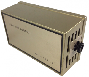
THE H600A CONTROLS EITHER A HUMIDIFIER OR DEHUMIDIFIER, IN RESPONSE TO RELATIVE HUMIDITY CHANGES IN THE SPACE. USED WITH AIR CONDITIONING SYSTEMS, THE H600A CONTROLS MILDEW.
The H600A has spdt switching to operate humidification equipment on RH fall or dehumidification equipment on RH rise.
- The sensing element is a moisture sensitive nylon ribbon wound around three bobbins to give four element control. This construction enables the controller to respond to small changes in relative humidity over a wide ambient temperature range.
- Switches line or low voltage loads up to the maximum rating of the dustproof snapacting switch.
- Attractive contemporary cover styling.
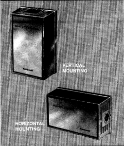
- Mounts vertically on standard junction box.
- Removable setting knob prevents tampering.
- TRADELINE models include alternate horizontal faceplate.
- Plastic locking cover; setting knob also acts as cover removal tool.
This is a legacy product document supported by Resideo. This product is no longer manufactured.
HUMIDITY CONTROLS


TRADELINE MODELS
TRADELINE models are selected and packaged to provide ease of stocking, ease of handling, and maximum replacement value. TRADELINE model specifications are the same as those of standard models except as noted below.
TRAOELINE MODEL. AVAIL.ABLE:
H600A Humidity Controller.
TRADELINE FEATURE:
- Includes faceplate for horizontal mounting.
ADDITIONAL FEATURES:
- TRADELINE pack with cross reference label and special instruction sheet.
STANDARD MODELS
MODEL:
H600A Humidity Controller.
SWITCHING: Spdt, snap-acting dustproof switch.
ELECTRICAL RATINGS (A):
| DEHUMIDI- FIER (RED
TO YELLOW) |
HUMIDIFIER
(RED TO BLUE) | |||
| 120
Vac |
240
Vac |
120
Vac |
240
Vac | |
| Full Load | 3.85 | 4.4 | 2.2 | |
| Locked Rotor | 4-5.0 | 22.8 – |
26.4 | 13.2 |
| Resistive | 8.0 | 4.0 | ||
Pilot Duty: 50 VA at 24 V, 120 VA at 120 V or 240 V.
RELATIVE HUMIDITY RANGE: 20 to 80 percent.
DIFFERENTIAL: Nonadjustable, 5 percent nominal.
MAXIMUM AMBIENT TEMPERATURE: 125° F [52° CJ.
SET POINT ADJUSTMENT: Removable knob.
COVER: Plastic locking cover.
FINISH: Silver-bronze.
MOUNTING: Mounts vertically on standard 2 x 4 inch junction box with two mounting screws and backplate provided.
DIMENSIONS: See Fig. 1.

FIG. 1-H600A APPROXIMATE DIMENSIONS IN in. [mm IN BRACKETS].

WHEN PURCHASING REPLACEMENT AND MODERNIZATION PRODUCTS FROM YOUR TRADELINE WHOLESALER OR YOUR DISTRIBUTOR, REFER TO THE TRADELINE CATALOG OR PRICE SHEETS FOR COMPLETE ORDERING NUMBER, OR SPECIFY-
- Order number, TRADELINE, If desired.
IF YOU HAVE ADDITIONAL QUESTIONS, NEED FURTHER INFORMATION, OR WOULD LIKE TO COMMENT ON OUR PRODUCTS OR SERVICES, PLEASE WRITE OR PHONE:
- YOUR LOCAL HONEYWELL RESIDENTIAL SALES OFFICE (CHECK WHITE PAGES OF PHONE DIRECTORY).
- RESIDENTIAL DIVISION CUSTOMER SERVICE HONEYWELL INC., 1885 DOUGLAS DRIVE NORTH MINNEAPOLIS, MINNESOTA 55422-4386 (612) 542-7500 IN CANADA-HONEYWELL LIMITED/HONEYWELL LIMITEE, 740 ELLESMERE ROAD, SCARBOROUGH, ONTARIO M1 P 2V9. INTERNATIONAL SALES AND SERVICE OFFICES IN ALL PRINCIPAL CITIES OF THE WORLD.

WHEN INSTALLING THIS PRODUCT
- Read these instructions carefully. Failure to follow them could damage the product or cause a hazardous condition.
- Check the ratings given in the instructions and on the product to make sure the product is suitable for your application.
- Installer must be a trained, experienced service technician.
- After installation is complete, check out product operation as provided in these instructions.
CAUTION
Disconnect power supply before making wiring connections to prevent electrical shock or equipment damage.
STANDARD INSTALLATION
LOCATION
Select a location about 5 ft. [1.5 m] above the floor in an area with good air circulation at average temperature. Do not mount the humidity controller where it may be affected by-
- drafts, or dead spots behind doors and in corners.
- hot or cold air from ducts.
- radiant heat from the sun, appliances, or fireplace.
- concealed pipes and chimneys.
- unheated (uncooled) areas behind the controller.
Minimum operating temperature is 60° F (16 ° C].
Maximum operating temperature is 125 ° F [52 ° C].
MOUNTING BACKPLATE

FIG. 2-MOUNTING OF H600A.
- Remove the mounting plate from the control assembly by loosening the captive mounting screw (Fig. 2). Slide control to the right and lift up.
- Route wiring from the controlled device to the H600A location (see Wiring).
- Fasten the mounting plate to the junction box using the two screws furnished.
WIRING
Disconnect power supply before making wiring connections to prevent electrical shock or equipment damage.

FIG. 3-MOUNTING THE CONTROLLER ON THE BACKPLATE.
All wiring must comply with applicable electrical codes and ordinances. Follow equipment manufacturer’s instructions, if available; otherwise, proceed as follows. Use wire nuts to make connections to the leadwires. If
one lead wire is not used on the H600A, insulate it by taping or using solderless connector. This will prevent accidental shorting.

FIG. 4-H600A WIRING DIAGRAM. CONNECT RED AND BLUE LEADWIRES TO HUMIDIFIER OR RED AND YELLOW LEADWIRES TO DEHUMIDIFIER.
CONNECTIONS FOR MILDEW CONTROL AND DEHUMIDIFICATION
Vacation homes that are unoccupied during the hot, humid summer weather are an invitation to mildew. The common cure is to simply select a moderate thermostat setting and let the air conditioner run. By applying either a low voltage thermostat in combination with an H600A dehumidistat or a W884E comfort center, mildew can be reliably prevented and air conditioning energy use can be optimized. The dehumidistat and thermostat should be wired in parallel such that by leaving the system switch in COOL and selecting appropriate set points; for example, 85 ° F (29° C] and 50 percent RH, either device will be able to control the air conditioning equipment. This independent operation will allow the higher temperature set point and still prevent mildew by controlling humidity. For wiring diagram, see Figs. 5 and 6.

FIG. 5-TYPICAL PARALLEL HOOKUP OF H600A WITH T87F THERMOSTAT AND Q539A SUBBASE FOR DEHUMIDIFICATION AND MILDEW CONTROL.

FIG. 6-TYPICAL SERIES HOOKUP OF H600A WITH T87F THERMOSTAT AND Q539A SUBBASE FOR DEHUMIDIFICATION AND MILDEW CONTROL.
MOUNTING H600A (STANDARD MODELS)
- Connect leadwires from controller to wires running from controlled equipment.
- Attach the H600A to the mounting plate by slipping it under the tabs (Fig. 3) and tightening the captive mounting screw.
- Place cover on controller. Using the adjusting knob supplied, tighten the cover locking screw securely. Remove adjusting knob.
TRADELINE INSTALLATION
The TRADELINE H600A may be mounted vertically or horizontally. For vertical mounting, follow standard installation instructions. For horizontal mounting, follow same instructions except mount backplate and control assembly horizontally. (The knob is on right side when the control is in the horizontal position.)
Before attaching the cover on a horizontally mounted TRADELINE controller, it is necessary to add the proper faceplate and scaleplate. The horizontal faceplate mounts over the existing faceplate on the cover with the setting indicator on the right end. Peel the wax paper backing from the horizontal faceplate. Carefully position one long edge of the faceplate to one long edge of the cover. Be sure faceplate is right side up. Apply the faceplate with a rolling motion to eliminate air bubbles. Buff the surface of the faceplate with finger or soft cloth. The setting indicator scaleplate mounts on the right end of the cover. Remove the vertical scaleplate by lifting the tabs with a screwdriver. Position the horizontal scaleplate over the setting indicator. Bend the tabs around the vent holes using a screwdriver. Attach cover using the setting knob to tighten the cover locking screw on the left end of the cover.

SETTING
Adjust the relative humidity setting by inserting the adjustment knob into the hole in the center of the setting indicator. Turn until the pointer is opposite the desired setting. When adjustment is complete, remove knob to
prevent tampering.
OPERATION
The H600A (for humidifying) makes contact on a humidity fall to the set point minus the differential to start the humidifier. In most humidifier systems, the fan must be operating before the humidifier will start. An increase in humidity to the set point breaks the contacts and stops the humidifier. Before attaching the cover on a horizontally mounted TRADELINE controller, it is necessary to add the proper faceplate and scaleplate. The horizontal faceplate mounts over the existing faceplate on the cover with the setting indicator on the right end. Peel the wax paper backing from the horizontal faceplate. Carefully position one long edge of the faceplate to one long edge of the cover. Be sure faceplate is right side up. Apply the faceplate with a rolling motion to eliminate air bubbles. Buff the surface of the faceplate with finger or soft cloth.
The setting indicator scaleplate mounts on the right end of the cover. Remove the vertical scaleplate by lifting the tabs with a screwdriver. Position the horizontal scaleplate over the setting indicator. Bend the tabs around the vent holes using a screwdriver. Attach cover using the setting knob to tighten the cover locking screw on the left end of the cover. The H600A (for dehumidifying) makes contact on a relative humidity rise to the set point to start the dehumidifier. A decrease in relative humidity to the set point minus the differential breaks the switch contacts to stop the dehumidifier. Turn the control knob


CHECKOUT
After the control has been installed, turn the adjustment to OFF (to the stop). The system should be off. With the fan running, slowly turn the adjustment knob until the controlled equipment starts to operate. Advancing the adjustment to the ON stop will produce constant ON operation.