Honeywell Switching Relays User Guide


Honeywell Switching Relays

THE R4222, R8222, R4228 AND R8228 ARE GENERAL PURPOSE RELAYS FOR USE IN REFRIGERATION AND AIR CONDITIONING EQUIPMENT, APPLIANCES, VENDING MACHINES, AND OTHER APPLICATIONS REQUI RING GENERAL PURPOSE SWITCHING.
- R4222 and R8222 contacts are available for Powerpile (millivoltage), pilot duty, and power pole applications.
- R4228 and R8228 have power rated contacts only.
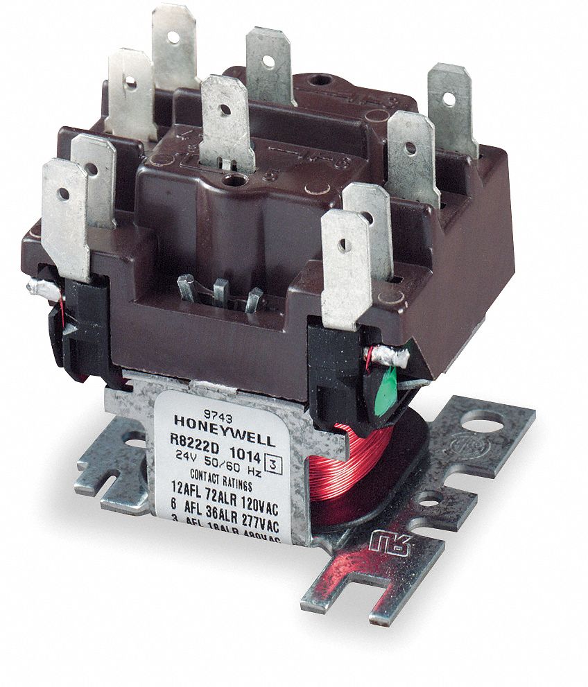
- R4222 and R4228 models have line voltage (120, 208/240, 277, or 480 Vac) coils. R8222 and R8228 models have low voltage (24 Vac) coils.
- Models available with a variety of switching configurations.
- Laminated magnet construction for high efficiency.
- Contacts rated for voltages up to 600 Vac.
- Molded terminal numbers and circuit diagram on top of relay provide easy identification for wiring and checking system operation.
- Relay constructed for high reliability.
- Quick-connect terminals are standard; double quick-connects available on coil terminals.
SPECIFICATIONS
IMPORTANT
THE SPECIFICATIONS GIVEN IN THIS PUBLICATION DO NOT INCLUDE NORMAL MANUFACTURING TOLERANCES. THEREFORE, THIS UNIT MAY NOT MATCH THE LISTED SPECIFICATIONS EXACTLY. ALSO, THIS PRODUCT IS TESTED AND CALIBRATED UNDER CLOSELY CONTROLLED CONDITIONS, AND SOME MINOR DIFFERENCES IN PERFORMANCE CAN BE EXPECTED IF THOSE CONDITIONS ARE CHANGED.
TRADELINE MODELS
TRADELINE models are selected and packaged to provide ease of stocking, ease of handling and maximum replacement value. TRADELINE model specifications are the same as those of standard models except as noted below.
TRADELINE MODELS AVAILABLE:
R4222B,D,N,V Switching Relay-line voltage.
R8222B,D,N,V Switching Relay-low voltage.
R4228A,B,D Heavy-duty Relay-line voltage.
R8228A,B,D Heavy-duty Relay-low voltage.
TERMINALS:
R4222, R8222, R4228D and R8228D have single quick-connects on poles, double quickconnects on coil terminals. R4228A,B and R8228A,B have double quick-connects on poles and double quick-connects on coil terminals. SWITCHING CONFIGURATIONS: R4222 and R8222, see Table II. R4228 and R8228, see
Table I. ADDITIONAL FEATURES:
TRADELINE pack with cross reference label and special instruction sheet
STANDARD MODELS:
R4222-General purpose relay: 120, 208/240, 277, and 480 Vac coil. R8222-General purpose relay: 24 Vac coil.
CONTACT RATINGS:
Power Pole (amperes per pole)- R4228-Heavy-duty general purpose relay: 120, 208/240, 277, and 480 Vac coil. R8228-Heavy-duty general purpose relay: 24 Vac coil.
| R4222,R8222C | 120 Vac | 208 Vac | 240 Vac | 277 Vac | 480 Vac |
| Inductive Full Load Locked Rotor |
12 60 |
6 | 6 | 6 | 3 18 |
| Resistive A and C Modelsb (equivalent resistive power) All Othersb |
20.8 (2.5 kW) 15 |
20.8 (4.3 kW) 15 |
20.8 (5.0 kW) 15 |
20.8 (5.7 kW) 15 |
10 (4.8 kW) 10 |
| Combined Ratings for A and C Modelsa Resistive (equivalent resistive power) Inductive |
12.5 (1.5 kW) +4.2 AFL 10.0 ALR |
12.5 (2.6 kW) +4.2 AFL 10.0 ALR |
12.5 (3.0 kW) +4.2 ALF 10.0 ALR |
12.5 (3.4 kW) +4.2 AFL 10.0 ALR |
6.25 (3.0 kW) +2.1 AFL +5.0 ALR |
| Horsepower | 3/4 hp | 3/4 hp | 3/4 hp | 3/4 hp | 3/4 hp |
- Combined ratings indicate that both a resistive and inductive load can be operated by each pole.
- Also rated 5 amp resistive at 600 volts.
- Underwriters Laboratories Inc. and CSA approved tor 50 cycle applications.
Ordering Information
WHEN PURCHASING REPLACEMENT AND MODERNIZATION PRODUCTS FROM YOUR TRADELINE WHOLESALER OR YOUR DISTRIBUTOR, REFER TO THE TRADELINE CATALOG OR PRICE SHEETS FOR COMPLETE ORDERING NUMBER, OR SPECIFY-
- Order number, include suffix leHer and specify TRADELINE if desired.
- Contact ratings.
- Coil ratings.
- Double quick-connects on coil terminals if desired.
- Accessories.
IF YOU HAVE ADDITIONAL QUESTIONS, NEED FURTHER INFORMATION, OR WOULD LIKE TO COMMENT ON OUR PRODUCTS OR SERVICES, PLEASE WRITE OR PHONE:
- YOUR LOCAL HONEYWELL RESIDENTIAL DIVISION SALES OFFICE (CHECK WHITE PAGES OF PHONE DIRECTORY).
- RESIDENTIAL DIVISION CUSTOMER SERVICE HONEYWELL INC., 111115 DOUGLAS DRIVE NORTH MINNEAPOLIS, MINNESOTA 55422-43116 (612) 542-7500
IN CANADA-HONEYWELL CONTROLS LIMITED, 740 ELLESMERE ROAD, SCARBOROUGH, ONTARIO M1P 2V9. INTERNATIONAL SALES AND SERVICE OFFICES IN ALL PRINCIPAL CITIES OF THE WORLD.
Pilot Duty Poles for R4222 and R8222 Only:
Minimum-3 VA at 24,120, and 480 Vac. Maximum-25 VA at24 Vac, 125 VA at 120, 240, and 480 Vac. Resistive-3 A at 277 Vac (0.75 power factor).
Power Pole (amperes per pole)- Powerpile (millivoltage) for R4222 and R8222 Only:
The normally open pilot duty contacts are rated for Powerpile (millivoltage) applications-0.25 A at 0.25 to 12 Vdc.
| R4228A,B; R8228A,B | 120 Vac | 208 Vac | 240 Vac | 277 Vac | 480 Vac |
| Inductive Full Load Locked Rotor |
16 18 96 72 |
18 72 |
18 72 |
12 72 |
5 30 |
| Resistivea (equivalent resistive power)
|
25 (3.0 kW) |
25 (5.2 kW) |
25 (6.0 kW) |
25 (6.9 kW) |
15 (7.2 kW) |
| Horsepower | 1 hp | 2 hp | 2 hp | 2 hp | 1.5 hp |
| R4228C,D; R8228C,D | 120 Vac | 208 Vac | 240 Vac | 277 Vac | 480 Vac |
| Inductive Full Load Locked Rotor |
5.5 15 |
5.5 | 5.5 | 5.5 | 3.0 8 |
| 15 | 15 | ||||
| Resistivea (equivalent resistive power) |
25 (3.0 kW) |
25 (5.2 kW) |
25 (6.0kW) |
25 (6.9 kW) |
12.5 (6.0 kW) |
| CombinecfRatingso Resistive (equivalent resistive power) Inductive |
20.8 (2.5 kW) +4.2 AFL 10.0 ALR |
20.8 (4.3 kW) +4.2 AFL 10.0 ALR |
20.8 (5.0 kW) +4.2 AFL 10.0 ALR |
20.8 (5.6 kW) +4.2 AFL 10.0 ALR |
10.4 (5.0 kW) +2.1 AFL 5.0 ALR |
| Inductive R4228E; R8228E | 120 Vac | 208 Vac | 240 Vac | 277 Vac | 480 Vac |
| Full Load Locked Rotor | 16 96 |
– |
18 72 |
5 30 |
5 30 |
| Resistivea | 25 | 25 | 25 | 15 | |
- Also rated 10 A resistive at 600 V.
- combined ratings indicate that both a resistive and an inductive load can be operated by each pole.
COIL RATINGS:
All coils meet Underwriters Laboratories Inc. requirements for Class B coils. If coil voltages other than those listed below are desired, contact your local Honeywell representative for additional information.

- Voltages listed are for the relay base mounted vertical. With the terminals pointing down, pickup voltage is increased by 12 percent.
- R8222D,G,J,N,R,T,V only.
NOTE: Pickup voltage varies with pole form. Specific models will have lower tolerance than shown above.
TERMINALS: Quick-connects are provided as shown:
| MODEL | TERMINALS | NUMBER OF QUICK-CONNECTS | ||
| SINGLE | DOUB LE | |||
| R4222 & R8222 |
Coil | Std. | Opt. | |
| Load | Std. | |||
| R4228 & R8228E R4228A,B& R8228A,B |
Coil | – | Std. | |
| Load- | – | Std. | ||
| R4228C,D & R8228C,D |
Load | Std. | – | |
MOUNTING: Use 2 screws (up to No. 10 size) through holes in the metal base. Base is designed for easy replacement of competitive relays.
AMBIENT TEMPERATURE RANGE: Minus 20 F [minus 29 C] to 155 F [68 CJ. DIMENSIONS: See Fig. 1.
The following tables give switching configurations, contact ratings, and terminal designations for the switching relays. For example, the R4222A is a spst switching relay with normally open power rated contacts. The R4222K is a spst relay with normally open contacts rated for pilot duty applications. Electrical connections to the A and K models would be made to terminals 1 and 3.
TABLE 1-R4228,R8228


TABLE 11-R4222, R8222


ACCESSORIES:
- 129384A Case and Cover Assembly.
- 4074BVJ Receptacle with 8 color-coded plug-in leadwires and retaining bail, for panel mounting applications; see Fig. 2.
- Q633A1003-4 x 4 plate-mounted relay receptacle with metal relay cover and 8 color-coded plug-in leadwires.
NOTE:- Use the receptacle in applications within the current carrying rating of the wire size and quick-connect terminal being used.
- The receptacle will accept relays with double quick-connect terminals.
- 135959 Receptacle only. Leads and quick-connect terminals are not supplied with the receptacle.
NOTE: Not all standard quick-connect terminals will be adequately retained in this receptacle. It is recommended that a quick-connect terminal with 0.016 inch [0.406 mm] maximum material thickness be used (0.012 inch (0.305 mm] preferred). The maximum permissible dimension between the rolls is 0.115 inch [2.92 mm]. These requirements are met by AMP, Inc. Faston “250” series terminal No. 42100-1 quickconnects or equivalent. - 135887 Wire Bail only.
- 137881A Adapters for converting 1/4 inch [6.4 mm] quick-connects to No. 6 screw terminals (bag of eight). UNDERWRITERS LABORATORIES INC.
COMPONENT RECOGNIZED:
R4222 and R8222 models: A to H,J,U,V,W,Y,Z; File
No. E59779; Guide No. NLDX2.
R4222 and R8222 models: K,L,M,N,P,Q,R,S,T; File
No. E49809; Guide No. NKCR2.
R4228 and R8228 models: A,B,C,D,E; File No.
E59779; Guide No. NLDX2.
CANADIAN STANDARDS ASSOCIATION COMPONENT CERTIFIED:
R4222 and R8222: File No. LR35066; Guide No. 184-N-13.13.
R4228 and R8228: File No. LR35066; Guide No. 184-N-13.13.

INSTALLATION:
WHEN INSTALLING THIS PRODUCT …
- Read these instructions carefully. Failure to follow them could damage the product or cause a hazardous condition.
- Check the ratings given in the instructions and on the product to make sure the product is suitable for your application.
- Installer must be a trained, experienced service technician.
- After installation is complete, check out product operation as provided in these instructions.
CAUTION:
Disconnect power supply before beginning installation to prevent electrical shock or equipment damage.
LOCATION
Mount the relay on a flat, solid surface as close as possible to the equipment being controlled. The relay may be mounted in any position except with the terminals pointed down. Secure in place with two screws through holes or slots in the mounting base or as shown in Fig. 3 or 4. See Fig. 1 for mounting dimensions.

FIG. 3-MOUNTING RELAY ON PANEL WITH SHEAR FORMED TAB AND ONE SCREW.
WIRING
Disconnect power supply before connecting wiring to avoid electrical shock or equipment damage. All wiring must comply with local codes and ordinances. Crimp female quick-connects to the system wires and attach to the male quick-connect terminals of the relay. The relay has molded terminal numbers and circuit diagram for easy identification when wiring. Fig. 6 shows the location and circuits of all models. Do not exceed contact and coil ratings when wiring into system.
Leadwires are provided with the 135959 Receptacle in 4074BVJ Bag Assembly for additional relay pole positions. Insert the required leadwires in the relay receptacle as follows.
Determine the leadwire colors required for the relay and application desired. Push the leadwire terminal into the receptacle plate from the side stamped with the numbers (Fig. 5). When inserting the leadwire, the tang on the quick-connect terminal must align with the small clearance slot in the terminal opening. Press the terminal in until it locks in place.

FIG. 4-RELAY MOUNTING USING RECEPTACLE AND RETAINING BAIL.

FIG. 5-BOTTOM OF 135959 RECEPTACLE SHOWING LEADWIRE INSTALLATION.
CHECKOUT
Operate the relay and controlled equipment to make sure that relay pulls in when the coil is energized and that controlled equipment operates as intended.


FIG. 6-R4222/R8222, R4228/R8228 CIRCUIT AND TERMINAL DESIGNATION.
Honeywell Inc.
1885 Douglas Drive N. Golden Valley, MN 55422-4386
International Sales Offices in all principal cities of the world. Manufacturing in Australia, Canada, Finland, France, Germany, Japan, Mexico, Netherlands, Spain, Taiwan, United Kingdom, U.S.A.