Honeywell HM700A1000 Electrode Steam Humidifier Installation Guide


HM700A1000 Electrode Steam Humidifier
QUICK INSTALLATION GUIDE
This is a legacy product document supported by Resideo. It is no longer manufactured
TOOLS & SUPPLIES NEEDED
- Screwdriver
- Shut-off water valve
- Wrench
- Waterline (LDPE or Copper)
- Pliers
MOUNTING
Requirements
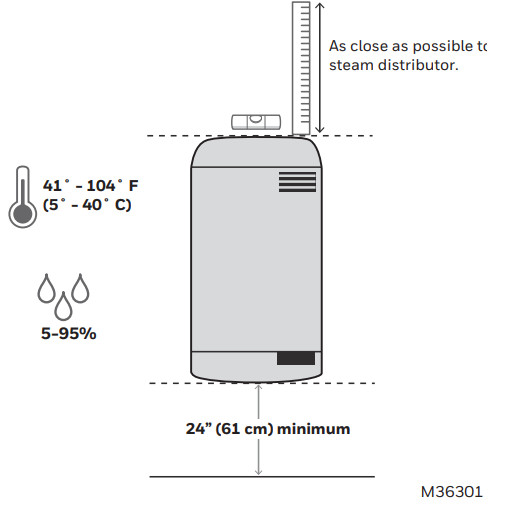
- Wall mount, minimum of 24 inches above the floor.
- The unit must be level.
- The location must have ambient temp between 41° and 104° F.
- The location must have a relative humidity of 5-95%.
- Allow 36-inch front clearance.

Mounting Process
- Preparation: use #8 screws at least 2” (5 cm) in length. Mount on 2×4 studs (or stronger) vertical surface.
- Install the rst screw at least 43.5 in. above the oor. Leave 1/4” (6 mm) of the shaft exposed for hanging the unit.
- Hang unit from top screw using the key-hole on back and ensure it is level.
- Secure unit with the second screw driven through the hole at the bottom.


PLUMBING
Supply Requirements
- Use potable water;
- DO NOT use reverse osmosis or de-ionized water.
- Pressure: 30-100 PSI;
- Conductivity: 125-1250 microsiemens;
- Temperature: 34-68° F (1-20° C).
Supply Plumbing

Drain Line Installation Process


ELECTRICAL
High Voltage Wiring
Requirements
- The humidifier MUST be connected GFCI circuit.
- 15 amp, 120/240-volt circuit required.
- The local disconnect must be installed for future servicing.
- Wiring must be performed by a licensed electrician.
High Voltage Wiring Install Process
Hard wire the unit to local circuit disconnect as shown below.
- Connect ground to the peg at the right.
- Connect neutral to terminal 1 (or hot, in the case of 240 volt).
- Connect hot to terminal 5.
- Insert jumper wire:
120 Volt: use the yellow jumper wire (supplied) to connect terminals 1 & 4.
- Remove the ground wire screw from the case body.
- Clip the other end of the green ground wire as close as possible to the drain valve. Remove the cut wire.


Low Voltage Control Wiring
Requirements
- 18 AWG solid wire minimum.
- Keep control wires as short as possible.
Control Wiring
Standard wiring only includes connecting terminals 1 and 2 to the thermostat.
For details on other wiring configurations, please refer to the product manual.
Honeywell recommends that all installations use Air Proving to ensure steam is only distributed when the fan is active.

Automation and Control Solutions
Honeywell International Inc.
1985 Douglas Drive North
Golden Valley, MN 55422
customer.honeywell.com
®U.S. Registered Trademark
© 2016 Honeywell International Inc.
33-00162EFS—03 M.S. Rev. 08-16
Printed in United States