Honeywell SOLDERING WIRE LEADS ON PRECISION HERMETIC THERMOSTATS Installation Guide
INSTALLATION INSTRUCTIONS FOR 50029956
SOLDERING WIRE LEADS ON Issue B
PRECISION HERMETIC THERMOSTATS

IMPROPER INSTALLATION

DO NOT USE these products as safety or emergency stop devices or in any other application where failure of the product could result in personal injury.
Failure to comply with these instructions could result in death or serious injury.
GENERAL INFORMATION
Ensure the soldering operation is done in a controlled environment, including:
- Temperature is 24°C ±5.6°C [75°F ±10°F], with a maximum humidity of 60%.
- The soldering area has a minimum of 1076 lux [100 foot candles] of light at the work surface.
PREPARATION
- Set soldering pot to 260°C ±14°C [500°F ±25°F].
- Clean wire leads with isopropyl alcohol or cleaning solvent.
SOLDERING
1. Immerse wire lead into flux prior to tinning. Dip the fluxed end of the lead into the molten solder. As the solder starts to wet the strands, slowly lower the wire into the solder and let the wire remain for 6 s. Solder must uniformly wet the strands a minimum of 0,79 mm [0.031 in] from the insulation.
2. Ensure soldering iron tip is clean and free of oxidation. Set soldering iron temperature to 316°C ±14°C [600°F ±25°F]. Clean tip frequently during soldering to remove oxidation. This may be done with a wet sponge. (A dirty tip requires more time to solder.)
3. Immerse the surface of the terminal and wire lead into the flux. The wire should be bent at a 90° angle with a minimum radius of one wire diameter. Ensure there are no nicked or broken strands. Insert the wire lead into the terminal hole.
4. Crimp the wire lead over ensuring no wire strands are nicked or broken.
5. Apply a heat sink to the terminals. (See Figure 1.)
Figure 1. Heat Sinks
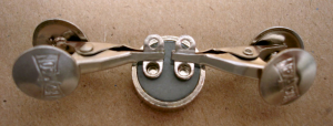

6. Position the leads so there is no movement during the soldering process.
7. Apply the soldering iron to the joint at a position near the midpoint of the mechanical wrap and heat to flow the solder. Ensure the joint is not heated longer than 10 s. (If this time exceeded, heat may migrate to the hermetic glass, cracking the glass and damaging hermetic seal integrity.
8. Apply sufficient solder so that it covers the wire lead over the extent of the wrap. The solder should not completely obscure the extent of the wrap. Do not allow solder to flow into the terminal well. (This may crack the glass and damage hermetic seal integrity.)
9. Remove solder, then remove soldering iron with a wiping motion.
10. Allow the joint to cool naturally, ensuring the parts do not move during cooling. Do not use water or any other solution to cool the joint.
AFTER JOINT HAS COOLED
- Remove heat sinks.
- Remove residual flux using Isopropyl alcohol or cleaning solvent.
- Inspect to ensure that:
• There are no cold solder joints.
• There are no nicked or broken strands.
• There is no solder in the terminal well.
• All flux has been removed.

FOR MORE INFORMATION
Honeywell Sensing and Internet of Things services its customers through a worldwide network of sales offices and distributors. For application assistance, current specifications, pricing, or the nearest Authorized Distributor, visit sps.honeywell.com/ast or call:
USA/Canada +302 613 4491
Latin America +1 305 805 8188
Europe +44 1344 238258
Japan +81 (0) 3-6730-7152
Singapore +65 6355 2828
Greater China +86 4006396841
WARRANTY/REMEDY
Honeywell warrants goods of its manufacture as being free of defective materials and faulty workmanship during the applicable warranty period. Honeywell’s standard product warranty applies unless agreed to otherwise by Honeywell in writing; please refer to your order acknowledgement or consult your local sales office for specific warranty details. If warranted goods are returned to Honeywell during the period of coverage, Honeywell will repair or replace, at its option, without charge those items that Honeywell, in its sole discretion, finds defective. The foregoing is buyer’s sole remedy and is in lieu of all other warranties, expressed or implied, including those of merchantability and fitness for a particular purpose. In no event shall Honeywell be liable for consequential, special, or indirect damages.
While Honeywell may provide application assistance personally, through our literature and the Honeywell web site, it is buyer’s sole responsibility to determine the suitability of the product in the application.
Specifications may change without notice. The information we supply is believed to be accurate and reliable as of this writing. However, Honeywell assumes no responsibility for its use.
Honeywell Advanced Sensing Technologies
830 East Arapaho Road
Richardson, TX 75081
sps.honeywell.com/ast

50029956-B-EN | B | 08/21
© 2021 Honeywell International Inc. All rights reserved.