Panasonic NN-TK81LC Microwave Oven Installation Guide


| Cabinet | Trim kit |
| 23 7⁄16” (596 mm) | NN-TK81LC |
Read carefully and keep these installation instructions.
© Panasonic Appliances Microwave Oven (Shanghai) Co., Ltd. 2021

- This Trim Kit is designed for use only with the Panasonic Microwave Oven listed in the table below, for installation into a cabinet.
- The dimensions and ground clearance of the cabinet opening must be as indicated in Figure 1 on pages 6-8.
- For safe use of your microwave oven, do not alter or modify any part of this kit or the microwave oven.
- The microwave oven must be used with a properly grounded 3-prong receptacle in compliance with the National Electrical Code, as well as any applicable local regulations. Refer also to the microwave operating instructions for other safety and electrical requirements.
- The microwave oven must be unplugged from the wall receptacle before attempting the installation of this kit.
- Save these instructions for local inspection and relocation of the microwave oven.
- Use caution so that the power cord is not pinched during installation.
- The diagrams in these instructions may vary from the actual unit and is only for reference.
| Trim kit | Panasonic Microwave Oven Models |
| NN-TK81LC | NN-CS89LB |
Parts List
Tools Needed: Measuring tape, pencil, Phillips screwdriver, Ø 2 (5 /64 ” ) mm drill
Parts Supplied

Installation Diagram

| Trim Kit Dimensions | |
| NN-TK81LC | |
| Width | 237 /16″ (596 mm) |
| Height | 197 /16″ (494 mm) |
| Depth (Thickness) | ¾” (20 mm) |
Cabinet Diagram and Dimensions


Microwave Oven Preparation


Put the longest tape on the right side of the oven and duct, put the rest two tapes on top of the oven and duct.
Spring lock Installation

Drill six pilot holes on both sides of the cabinet. (Use the supplied position diagram)

Lower Duct Installation

6-1. Align the base bracket assembly
Position Base Bracket Assembly on a cabinet shelf. The front end of the Base Bracket Assembly should align flush with the front edge of the shelf.

Support plate (left) Installation

Trim Frame (downside) and Support plate (right) Installation

8-1. Insert the support plate pin (left side) into the left pinhole of the Trim Frame (downside).
8-2. Then insert the support plate pin (right side) into the right pinhole of the Trim Frame (downside).
8-3. Align the right support plate close to the right side of a base bracket assembly and the front of the cabinet, then tighten the two screws.
Spring Installation

Trim frame (upside) mounting brackets Installation


Note: Catch could be broken if over-pressing at the center area
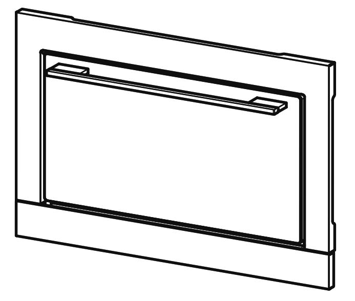
Trim Kit Preparation
Trim Frame

Microwave Oven Installation
Complete the assembly

Trim Kit/Finishing Installation
Complete the assembly

Note: Put upside of strikes into position then push the Trim Kit up to install the downside.
Removal of the water tank and drip tray


Troubleshooting
- The downside and upside of the trim frame are not aligned
- The surface of the trim frame is not aligned
• Cause and remedy/Cause et solution The support plates are not installed in the correct position. Remove the support plate and reinstall. See page 13. - The space beside the oven is not even.
- The space for the Upper and lower sides of the oven is not even.


PA0121-10621
Printed in China