Dell EMC DSS 8440 User Manual
Dell EMC DSS 8440 User Manual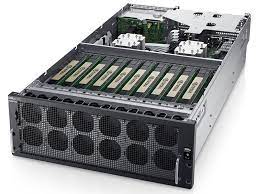

Notes, cautions, and warnings
NOTE: A NOTE indicates important information that helps you make better use of your product


Dell EMC DSS 8440 system overview
The Dell EMC DSS 8440 system is a 4U system that supports:
- Two Intel Xeon Scalable processors
- Twenty-four DIMM slots
- Four AC power supply units
- Support up to 8 SAS, SATA drives, or NVMe drives. The total of SAS or SATA + NVMe drives is 10
For more information about supported drives, see the Drive specifications section.
NOTE: All instances of SAS, SATA drives, SSDs, or NVMe drives are referred to as drives in this document, unless specified otherwise.
Topics
- Front view of the system
- Rear view of the system
Front view of the system

NOTE: The handles in front control panel are not intended to lift the system.
Control panel
Figure 1. Right control panel view

- Power-on indicator/power button
- System-health indicator
- System identification button
Rear view of the system
Figure 2. Rear view of the system

- Slots-4, 5, 14, 15
- Slots-[19..16]
- Drive-[0..9]
- Slot-1
- Slot-3
- ID
- Power-Jack
- RJ45
- DB9
- DB15
- 2x USB-3.0 12. 2x RJ45 + 2xSFP+
- Power Supply 1 to 4
Technical specifications
The technical and environmental specifications of your system are outlined in this section.
Chassis dimensions

Table 1. Dell EMC DSS 8440 chassis dimensions
| Xa | Xb | Y | Za | Zb | Zc |
| 483.2 mm (19.02 inches) |
444.6 mm (17.50 inches) |
174.8 mm (6.88 inches) |
With bezel: 872.0 mm (34.33 inches) |
836.5 mm (32.93 inches) |
850.2 mm (34.47 inches) |
Chassis weight
Table 2. Chassis weight
| System | Maximum weight (with all drives) |
| DSS 8440 (2 CPU/ 10 GPU/ 10 HDD/ 1 H730P+/ 1 CX5) | 46.3 Kg (102.07 lb) |
Processor specifications
TheDell EMC DSS 8440 system supports two Intel Xeon Scalable processors with up to 24 cores per processor.
NOTE: Ensure that both the processors are populated and both are of the same type or model.
PSU specifications
The system supports up to four redundant AC power supply units (PSUs).
Table 3. PSU specifications
| Functions | 2400W Power supply |
| Input | |
| Input voltage range | AC input : 200Vac~240Vac @ High line : 2400W |
| Frequency | 50/60 Hz |
| Efficiency | VIN=230Vac ● 89% @ 10% load ● 93% @ 20%load ● 94% @ 50% load ● 100% load @ 91.5% load |
| Power Factor | PF at 230Vac/50,60 Hz ● > 0.88 @ 10% load ● > 0.94 @ 20% load ● > 0.98 @ 50% load ● > 0.99 @ 100% load |
| iTHD | 230Vac/60 Hz ● 25% @ 0% load ● 25% @10% load ● 10% @ 20% load ● 5% @50% load ● 4% @100% load |
| Hold-up Time | 13.5ms @ 100% load |
| Conducted EMI | Class A |
| Radiated EMI | Class A |
| Functions | 2400W Power supply |
| Output | |
| Main DC Output | |
| Voltage Regulation | 12.2V +/-5% |
| Output current | 196.72A @ high line |
| Standby Output | |
| Voltage Regulation | 12V +/-5% |
| Output current | 3.5A |
Cooling fans specifications
The Dell EMC DSS 8440 system supports up to twelve 60 mm x 60 mm (square) cooling fans.
System battery specifications
The Dell EMC DSS 8440 system supports CR 2032 3.0-V lithium coin cell system battery.
Expansion card riser specifications
The Dell EMC DSS 8440 system supports up to 10 x Dual width full height PCIe slots and rear I/O x8 full height full length x16 PCIe slots.
GPU specifications
The Dell EMC DSS 8440 system supports up to 16 GPU:
- Double wide
- Nvidia V100 16 GB/32 GB GPU card
- Graph core C2 IPU card
- Nvidia T4 GPU card
- Nvidia A100 GPU card
- Nvidia A40 GPU card
Table 4. Nvidia Tesla T4 GPU configurations
| Nvidia Tesla T4 number | ||||
| PCIe Dummy bracket | 8 GPUs | 8 GPUs + optional riser | 12 GPUs | 16 GPUs |
| Quantity | 12 | 8 | 8 | 5 |
| Position(slot) | 4, 5, 6L, 7L, 8L, 9L, 10L, | 6L, 7L, 8L, 9L, 10L, 11L, | 6L, 7 L, 8L, 9L, 10L, 11L, | 6L, 7L, 8L, 9L, 10L |
| 11L, 12L,13L, 14, 15 | 12L , 13L | 12L, 13L | ||
Table 5. Nvidia A100/A40 GPU configurations
| N v i d i a A 1 0 0 / A 4 0 | |||
| Configurations | 4 GPUs | 8 GPUs | 10 GPUs |
| Slot | 8, 9, 10, 11 | 6, 7, 8, 9, 10, 11, 12, 13 | 5, 6, 7, 8, 9, 10, 11, 12, 13, 15 |
| NVLink Bridge | [8,9][10,11] | [6,7][8,9][10,11][12,13] | N/A |
Memory specifications
Table 6. Memory specifications
|
DIMM type |
DIMM rank |
DIMM capacity |
Dual processors | |
| Minimum RAM | Maximum RAM | |||
| RDIMM | Dual rank | 32 GB | 64 GB | 768 GB |
| RDIMM | Dual rank | 16 GB | 32 GB | 384 GB |
| RDIMM | Single rank | 8 GB | 16 GB | 192 GB |
NOTE: Ensure that all the memory slots are populated either with DIMMs or DIMM blanks.
NOTE: It is recommended to have all DIMMs of the same type.
Drive specifications
The Dell EMC DSS 8440 system supports 10 x 2.5 inch hard drives with following configurations:
- Drive 0–1: Support SATA/SAS only
- Drive 2–7: Support SATA/SAS/NVMe only
- Drive 8–9: Support NVMe only
Ports and connectors specifications
USB ports specifications
Dell EMC DSS 8440 system supports two USB 3.0 ports available through back panel and one internal USB 3.0 port on system board.
COM port specifications
Dell EMC DSS 8440 system supports one 9 pin 16550 compliant com ports available through the back panel.
VGA port specifications
Dell EMC DSS 8440 system supports one 15 pin VGA ports available through the back panel.
LOM port specifications
Dell EMC DSS 8440 system supports two 10GbE SFP+ ports and two 1GbE RJ-45 ports available through the back panel.
Storage controller specifications
The Dell EMC DSS 8440 system supports the following controller cards:
Table 7. Dell EMC DSS 8440 system controller cards
Internal controllers
- PERC H730P
- S140
Environmental specifications
The following details define the system level operating and non-operating environmental limits.
Table 8. Maximum Temperature:
| Maximum Temperature: | |
| Operation: | |
| Fan normal | 10°C–35°C. (Maximum temperature is reduced by 1°C/300m (1°F/547ft) above 950 m (3117 ft)). |
| One rotor fan failure | 10°C -35°C. (Maximum temperature is reduced by 1°C/300m (1°F/547ft) above 950 m (3117 ft)). |
| Non-Operation | -40°C to 65°C |
Table 9. Humidity
| Humidity | |
| Operation | 10% to 80% RH, non-condensing |
| Non-Operation | 5% to 95% RH, non-condensing |
Table 10. Maximum Altitude
| Maximum Altitude | |
| Operation | 10,000 ft |
| Non-Operation | 30,000 ft |
System diagnostics and indicator codes
Table 11. System diagnostics and indicator codes
| Icon | Indicator, button, or connector | Description |
| Power-on indicator, power button | The power-on indicator lights when the system powered on. The power button controls the power supply output to the system. NOTE: On APCI-compliant operating system, turning off the system using power button causes the system to perform a graceful shutdown before power to the system is turned off. | |
| Health indicator | Indicates the health of the system. ● If the system is powered on and in good health, the indicator lights solid blue. No corrective action is required ●The indicator blinks amber if the system is on or in standby, and if any error exists (For example, a failed fan). See the System Event Log or system messages for the specific issue. For information about the event and error messages generated by the system firmware and agents that monitor system components, go to qrl.dell.com > Look Up > Error Code, type the error code, and then click Look it up.Invalid memory configurations can cause a blank screen or no video output. See the Getting help section. | |
| System identification button | The identification button on the front and back panels can be used to locate a particular system within a rack. When one of these buttons is pressed, the corresponding system identification button on the back flashes until one of the buttons is pressed again. Press the system identification button to turn the system ID on or off. If the system stops responding during POST, press and hold the system ID button for more than five seconds to enter BIOS progress mode. To reset iDRAC (if not disabled in F2 iDRAC setup), press and hold the button for more than 15 seconds. |


NIC indicator codes
Each NIC on the back panel has an indicator that provides information about the network activity and link status. The activity LED indicates whether the NIC is connected or not. The link LED indicates the speed of the connected network.

Figure 4. NIC indicators
- link indicator
- activity indicator
Table 12. NIC indicators
| Convention | Status | Condition |
| A | Link and activity indicators are off. | The NIC is not connected to the network. |
| B | Link indicator is green. | The NIC is connected to a valid network at its |
| maximum port speed (1 Gbps or 10 Gbps). | ||
| C | Link indicator is amber. | The NIC is connected to a valid network at less than its |
| maximum port speed. | ||
| D | Activity indicator is flashing green. | Network data is being sent or received. |
Power supply unit indicator codes

Figure 5. AC PSU status indicator
- AC PSU status indicator/handle
Table 13. AC PSU status indicators
| Convention | Power indicator pattern | Condition |
| A B
c
D E |
Green
Flashing green
Flashing green and turns off.
Flashing amber Not illuminated |
A valid power source is connected to the PSU and the PSU is operational. When the firmware of the PSU is being updated, the PSU handle flashes green. CAUTION: Do not disconnect the power cable or unplug the PSU when updating firmware. if firmware update is interrupted, the PSUs do not function. When hot-adding a PSU, the PSU handle flashes green five times at 4 Hz rate and turns off. This indicates a PSU mismatch with respect to efficiency, feature set, health status, and supported voltage. CAUTION: If four PSU are installed, the four PSUs must have the same type of label; for example, Extended Power Performance (EPP) label. Mixing PSU from previous generations of PowerEdge servers is not supported, even if the PSU has same power rating. This results in a PSU mismatch condition or failure to turn the system on. CAUTION: When correcting a PSU mismatch, replace only PSU with the blinking indicator. Swapping the PSU to make matched pair can result in an error condition and unexpected system shutdown. To change from a high output configuration to a low output configuration or vice versa, you must turn off the system CAUTION: The 120 V AC PSU is not recommended for this system. Operating at 120 V AC results in the 2400W PSU de-rating to only 1400W, which can affect power redundancy policy and possibly system throttling. CAUTION: If four PSUs are used, they must be of the same type and have the same maximum output power. Indicates a problem with the PSU. Power is not connected to the PSU. |
Getting help
Contacting Dell EMC
Dell EMC provides several online and telephone based support and service options. If you do not have an active internet connection, you can find contact information about your purchase invoice, packing slip, bill, or Dell EMC product catalog. Availability varies by country and product, and some services may not be available in your area. To contact Dell EMC for sales, technical assistance, or customer service issues:
Steps
- Go to www.dell.com/support/home.
- Select your country from the drop-down menu on the lower right corner of the page.
- For customized support:
- Enter your system Service Tag in the Enter your Service Tag field.
- Click Submit.
The support page that lists the various support categories is displayed.
- For general support:
- Select your product category.
- Select your product segment.
- Select your product.
The support page that lists the various support categories is displayed.
- For contact details of Dell EMC Global Technical Support:
- Click Contact Technical Support.
- Enter your system Service Tag in the Enter your Service Tag field on the Contact Us webpage.
Documentation feedback
You can rate the documentation or write your feedback on any of our Dell EMC documentation pages and click Send Feedback to send your feedback.
Recycling or End-of-Life service information
Take back and recycling services are offered for this product in certain countries. If you want to dispose of system components, visit www.dell.com/recyclingworldwide and select the relevant country