Honeywell TARS-IMU Sensors for Traction Control and Stabilization User Guide
Honeywell TARS-IMU Sensors for Traction Control and Stabilization

Background
In the past, off-road wheeled and track equipment has been primarily controlled by the operator of the equipment. This includes equipment for the agriculture, construction, oil and gas, and defense industries. However, with operator control of the equipment only, the drive wheels or tracks could begin to slip or spin before the operator becomes aware of the issue. This could result in damage to the equipment or landscape and potential operator injury. As a result, more time and cost can be incurred to complete a jobsite. Also as experienced operators retire or leave the trades, newer and inexperienced operators can add additional time and cost as they ascend the learner curve on use of the equipment.
Solution
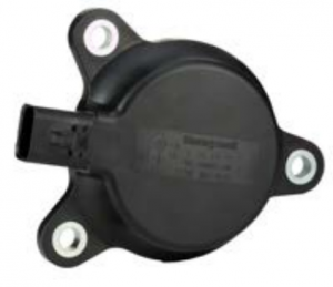
The Honeywell Transportation Attitude Reference System, or TARSIMU, is a packaged sensor array designed to report vehicle angular rate, acceleration, and attitude data for demanding applications in industries such as heavy-duty, off-highway transportation.
TARS-IMU enables autonomous vehicle characteristics and enhances efficiency and productivity by reporting key data required to automate and monitor movements of vehicle systems and components. The sensor fusion algorithm can be customized for specific vehicle applications through on-board firmware, allowing movement data to be filtered for extraneous environment and vehicle movements.
The Honeywell TARS-IMU sensor array can be programmed to communicate with the operator and/or the control system for a predetermined set of values.
As more equipment becomes integrated with smart electronics, the equipment is able to operate more efficiently with inputs from the electronics and the operator. Reference the Honeywell TARS-IMU sensor as illustrated in the diagrams of Figures 1 and 2.
In the left diagram of Figure 2, the equipment is positioned as designed.
In the center diagram, the wheels or tracks begin to slip and/or spin with reference the front set. When the TARS sensor senses a movement that does not match the expected movement, the equipment through engine response, transmission, and/or drive train adjusts to return the equipment in a controlled manner (right diagram).
Features and Benefits
- Enhanced performance from IMU offers reporting of vehicle angular rate, acceleration and inclination (6 degrees of freedom)
- Ruggedized PBT thermoplastic housing design enables it to be used in many demanding applications and environments (IP67- and IP69K-certified)
- Advanced filtering of raw sensor data to minimize unwanted noise and vibrations, improving positioning accuracy
- Optional metal guard for added protection
- Supports 5 V and 9 V to 36 V vehicle power systems
- Operating temperature of -40°C to 85°C [-40°F to 185°F]
- Reduced power consumption
- Small form factor


In this example we can see that as the equipment begins to slip or spin the sensor detects movement and direction of that slippage, and signals from the sensor alerts the equipment control module. The system then can correct the equipment position in real-time, making it safer to operate, and reducing the possibility of equipment damage, potential landscape damage and potential operator injury.
This assistance will be found more often as the industry moves toward select fully autonomous systems. TARS-IMU can be a key piece in providing and reporting key machinery and implement data. With six degrees of freedom (see Figure 1), TARS-IMU reports the key movement data such as angular rate, acceleration, and inclination. Furthermore, the TARS IMU is equipped with customizable data filters; it can be tuned to reduce extraneous noise and vibration that would otherwise distort the valuable data.
The TARS-IMU utilizes a robust packaging design (IP67/IP69K) that makes it more resilient to the rigors of the construction industry. In addition, a wide operating temperature range of -40°C to 85°C makes it ready for use in many demanding tool and implement applications.

IMPROPER INSTALLATION
Failure to comply with these instructions could result in death or serious injury |

Warranty/Remedy
Honeywell warrants goods of its manufacture as being free of defective materials and faulty workmanship. Honeywell’s standard product warranty applies unless agreed to otherwise by Honeywell in writing; please refer to your order acknowledgement or consult your local sales office for specific warranty details. If warranted goods are returned to Honeywell during the period of coverage, Honeywell will repair or replace, at its option, without charge those items that Honeywell, in its sole discretion, finds defective. The foregoing is buyer’s sole remedy and is in lieu of all other warranties, expressed or implied, including those of merchantability and fitness for a particular purpose. In no event shall Honeywell be liable for consequential, special, or indirect damages.
While Honeywell may provide application assistance personally, through our literature and the Honeywell website, it is customer’s sole responsibility to determine the suitability of the product in the application.
Specifications may change without notice. The information we supply is believed to be accurate and reliable as of this printing. However, Honeywell assumes no responsibility for its use.
For more information
To learn more about Honeywell’s
sensing and switching products,
call 1-800-537-6945, visit sps.honeywell.com/ast,
or email inquiries to
Honeywell Advanced Sensing Technologies
830 East Arapaho Road
Richardson, TX 75081
sps.honeywell.com/ast
