Honeywell Sensors and Switches for Valves and Flow Meters User Guide


Honeywell Sensors and Switches for Valves and Flow Meters

Background
Flow meters can measure and regulate volumetric flow, velocity from which the volumetric flow is determined, and mass flow. Valves control or regulate the flow of gases or fluids by partially obstructing, opening or closing the pipeline that carries the media. In many applications, they are operated manually by a lever, pedal, or wheel. Valves are often used in oil and gas, chemical manufacturing, water reticulation and mining applications.
Automatic valves with diaphragms or pistons are often actuated by changes in pressure, temperature or flow.
Solutions
Honeywell manufactures a wide range of sensors and switches, from simple on/off switches to electronic sensors designed to deliver system control, fluid level indication, temperature regulation, along with protection from overheating and starting/stopping the compressor. Honeywell components provide enhanced reliability, minimize down time, and improve robustness in most harsh environments.
Various package options are available, including stainless steel, and those designed for hazardous and harsh-duty applications.
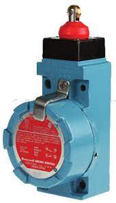
Hazardous-location limit switches : These specialized switches perform a number of functions, including monitoring the position of the valve stem, actuator or wheel position, providing on-off position on manual process valves, providing real-time valve status information for improved productivity and safety. As these limit switches are enclosed in an explosion-proof housing, any flame path is extinguished inside which mitigates the risk of causing an explosion at the switch part.
These switch components provide feedback for the user to take action in order to prevent explosions in hazardous environments. Hazardous location switches are employed in valves in outdoor, above-ground, potentially explosive environments such as oil and gas or water treatment applications.
Limit Switches: Employed to monitor the position of the valve stem or actuator, limit switches are primarily used on valves in non-explosive environments such as waste water treatment plants, power generation plant or other factory applications. They also allows users to remotely monitor the valve stem, actuator lever, or wheel position for improved productivity and reduced total installed cost in hazardous locations.

Wireless Limit Switches: Allows users to remotely monitor valve stem, actuator lever, or wheel position for improved productivity and safety, while reducing total installed cost with an economical wireless point-to-point solution.
Basic Switches: Snap-action switches monitor the position of the valve handle by indicating if the switch is actuated. These switches are employed on valves used in both non-explosive environments such as waste water treatment plants and/or other factory applications and also explosive/hazardous applications. In valve monitoring applications, basic switches perform position sensing on cams with no power consumption. In addition to valves, Honeywell’s V15W2 Series is suitable for use in hazardous environments such as refrigeration, HVAC, appliances, and paint booths.
Hall-effect Speed Sensors and Sensor ICs: In flow meter applications Honeywell’s speed sensors measure flow by monitoring revolutions of the impeller (an inside propeller). Each revolution of the impeller equates to the delivery of a certain amount of fluid. For example, if the user sets a fluid level of five gallons per minute, the speed sensor counts the impeller rotation so that the correct amount of fluid is delivered. In valve monitoring application, Hall-effect sensor ICS measure position sensing on cams.
Position Sensors: In flow meter applications, Hall-effect magnetic position sensors are used to determine valve position. In valve monitors, position sensors deliver continuous position status with enhanced reliability and accuracy.
Pressure Transducers and Switches: In valve actuator applications, pressure transducers and switches measure the pressure of the diaphragm to help regulate and control the flow within the pipeline. The sensors can measure differential pressure by comparing values across the valve. They can also give an indication of valve position related to opening and closing by measuring the pressure value at that time.
Figure 2. Sensing and Switching Products Used in Manual Process Valves

Hazardous Location Position Sensor
XYR6000 One Wireless™ Series Allows users to remotely monitor valve stem, actuator lever, or wheel position for improved productivity and safety, while reducing total installed cost in hazardous locations.
Part of a scalable ISA100 mesh network
Hazardous Area Limit Switch
MICRO SWITCH VPX/LSX/CX/BX/EX Series Monitors valve stem, actuator lever, or wheel position, providing real-time position status for improved productivity and safety in hazardous locations
Limit Switch
MICRO SWITCH HDLS, GLS, and Double Break Series Monitors valve stem, actuator lever, or wheel position, providing real-time position status for improved productivity and safety.
Figure 3. Sensing and Switching Products Used in Manual Process Valves with Actuators

APPLICATION NOTE: Sensors and Switches for Valves and Flow Meters | sps.honeywell.com/ast
Figure 4. Switches in Valve Actuators and Positioners

- Explosion-Proof Valve Position Indicator
MICRO SWITCH VPX • Valve position indicator in explosion-proof housing - Basic Switch
MICRO SWITCH BZ, V7, V15, V15W2, and ZW Series • Large, miniature, and subminiature basic switches - Hazardous Location Limit Switch
MICRO SWITCH LSX, CX, and BX Series • Premium limit switches in explosion-proof housing - Limit Switch
MICRO SWITCH HDLS, GL, and Double Break Series • Premium heavy duty and standard global limit switches
Figure 5. Sensing and Switching Products Used in Valve Actuators

- Hazardous Location Position Sensor
XYR6000 One Wireless™ Series Allows users to remotely monitor valve stem, actuator lever, or wheel position for improved productivity and safety, while reducing total installed cost in hazardous locations; part of a scalable ISA100 mesh. network - Hazardous Area Limit Switch
MICRO SWITCH™ LSX/CX/BX/EX Series Monitors valve stem, actuator lever, or wheel position, providing real-time position status for improved productivity and safety in hazardous locations. - Wireless Limit Switch
MICRO SWITCH™ HDLS and GLS Series Allows users to remotely monitor valve stem, actuator lever, or wheel position for improved productivity and safety, while reducing total installed cost with an economical wireless point-to-point solution. - Limit Switch
MICRO SWITCH™ HDLS, GLS, and Double Break Series Monitors valve stem, actuator lever, or wheel position, providing real-time position status for improved productivity and safety. - Position Sensor
SMART Position Sensor, SPS Series 75 mm Linear Monitors valve stem or actuator position. - Stainless Steel Media Isolated Pressure Sensor or Pressure Switch
MLH, PX2, or PX3 Series Pressure Sensor or HP, HE, ME, LP, or LE Series Pressure Switch Measures diaphragm pressure.

Types of Valves
Specifically, there are several main types of valves: 1) Manual process valves, 2) Valve actuators/positioners, 3) Valve monitors/indicators, 4) Valves and flowmeters, and 5) Sanitary and food/beverage valves.
Manual Process Valves : Manual process valves in industrial facilities control the flow of liquid, gas, slurry, or steam. Eighty percent require operators to manually open, close, or otherwise control the valve. At any given time, users may not know the actual position of the valve. Process plants, including refineries, chemical, pharmaceutical, and water treatment plants as well as power generation installations, all need a better way to verify status with or without human intervention, especially in hazardous or hard-to-reach locations. (See Figures 2 and 3)
Valve Actuators/Positioners : A valve actuator is a pneumatic or electric mechanism used in process control systems to automatically open or close valves. Actuators can be used with either linear or rotary valves in industrial, medical, food/beverage, and transportation applications. In standard valves, when the valve is given a command to open to a certain point, there is no feedback to verify that it has opened to that position. Valve positioners utilize a source of power to operate and continuously adjust a valve. The power source can be a manual gearbox or an electronic device with control and measuring devices; Available with hydraulic, pneumatic, and electric operating mechanics, these are often used in pipelines, process plants and in remote areas. Postioners can be used for opening or closing a valve to control the rate of fluid flow based on a signal from a central control system. With a valve positioner, the command is given and the valve positioner reads the opening, verifies position, and readjusts (if necessary) to the exact position needed which allows for excellent precision in the valve setting. (See Figures 4 and 5)
Valve Monitors/Indicators: Mechanical or electrical valve monitors and indicators are used in process control to show valve position. They provide an electrical signal, and sometimes visual feedback, to accurately monitor and verify that a valve is in the correct position. Valve monitors are mostly used in conjunction with a valve positioner/actuator to provide information from remote locations that are not easily accessed, or where power isn’t readily available. Potential applications include chemical, pharmaceutical, power generation and oil and gas processes. (See Figures 4 and 5)
Valves and Flowmeters: Valves control or regulate the flow of gasses or fluids by partially obstructing, opening or closing the pipeline that carries the media. Valves are often used in oil and gas, chemical manufacturing, water reticulation and mining applications. In many of these applications, the valves are operated manually by a lever, pedal or wheel. Automatic valves with diaphragms or pistons are often actuated by changes in pressure, temperature or flow.
Flow meters can measure and regulate volumetric flow, velocity from which the volumetric flow is determined, and mass flow. The turbine flow meter translates the mechanical action of the turbine rotating in the liquid flow around an axis into a user-readable rate of flow (gpm, lpm, etc.). The turbine wheel is set in the path of a fluid stream. The flowing fluid impinges on the turbine blades, imparting a force to the blade surface and setting the rotor in motion. Nearly all flow meters must be installed so that there is a significant run of straight pipe before and after the location of the flow meter. This is intended to allow the straight pipe run to “smooth out” any turbulence produced by the presence of valves, chemical injectors and diffusers, and changes in pipe direction. (See Figure 5)
Sanitary and Food/Beverage Valves: Sanitary and food and beverage valves are engineered for pressure control in sanitary (or “clean”) environments. They are usually manufactured with stainless steel for sanitary and high-purity applications. These valves are often constructed as a ball valve around a full bore design that ensures the product passes through the valve with no restrictions on the flow with minimal pressure drop.
Sanitary and food and beverage valves are often found in pharmaceutical, biotechnology, food and beverage, cosmetics, chemical and other industries where sanitary process control is required for steam, gases, and liquids such as water-for-injection systems.
Warranty/Remedy
Honeywell warrants goods of its manufacture as being free of defective materials and faulty workmanship during the applicable warranty period. Honeywell’s standard product warranty applies unless agreed to otherwise by Honeywell in writing; please refer to your order acknowledgment or consult your local sales office for specific warranty details. If warranted goods are returned to Honeywell during the period of coverage, Honeywell will repair or replace, at its option, without charge those items that Honeywell, in its sole discretion, finds defective. The foregoing is buyer’s sole remedy and is in lieu of all other warranties, expressed or implied, including those of merchantability and fitness for a particular purpose. In no event shall Honeywell be liable for consequential, special, or indirect damages.
While Honeywell may provide application assistance personally, through our literature and the Honeywell web site, it is buyer’s sole responsibility to determine the suitability of the product in the application.
Specifications may change without notice. The information we supply is believed to be accurate and reliable as of this writing. However, Honeywell assumes no responsibility for its use.
WARNING: PERSONAL INJURY
DO NOT USE these products as safety or emergency stop devices or in any other application where failure of the product could result in personal injury.
Failure to comply with these instructions could result in death or serious injury.
WARNING: MISUSE OF DOCUMENTATION
- The information presented in this product sheet is for reference only. Do not use this document as a product installation guide.
- Complete installation, operation, and maintenance information is provided in the instructions supplied with each product.
Failure to comply with these instructions could result in death or serious injury.
For more information
Honeywell Advanced Sensing Technologies services its customers through a worldwide network of sales offices and distributors. For application assistance, current specifications, pricing or the nearest Authorized Distributor, visit
sps.honeywell.com/ast or call :
Asia Pacific +65 6355-2828
Europe +44 (0) 1698 481481
USA/Canada +1-800-537-6945
Honeywell Advanced Sensing Technologies
830 East Arapaho Road
Richardson, TX 75081
sps.honeywell.com/ast
