Honeywell C7263 CO2 Sensors Installation Guide


INSTALLATION INSTRUCTIONS
APPLICATION
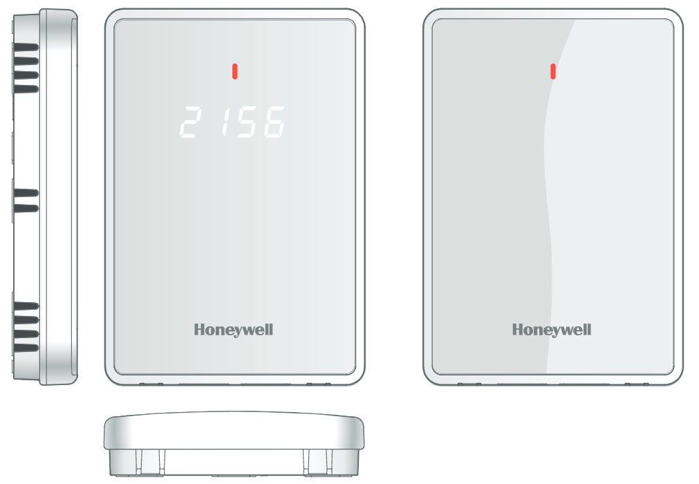
The C7233A & C7263A series are wall mount CO2 sensors that provide analog or digital output signals for demand control ventilation systems. They ensure improved indoor air quality while minimizing energy costs.
INSTALLATION
Before installation
- Read these instructions carefully. Failure to follow them could damage the product or cause a hazardous condition.
- Check the ratings given in the instructions and on the product to make sure the product is suitable for your application. The installer must be a trained, experienced service technician.
- After installation is complete, check out product operation as provided in these instructions.
Improper use can create dangerous situations.
Use in an application for sensing carbon dioxide only. For life-safety applications, this device can function only as a secondary or lesser
device.
Electrical Shock or Equipment Damage Hazard.
Can shock individuals or short equipment circuitry.
Disconnect power supply before installation.
Equipment Damage Hazard. Electrostatic discharge can short equipment circuitry.
Ensure that you are properly grounded before handling the unit.
CALIFORNIA PROPOSITION 65 WARNING :
This product can expose you to chemicals including lead, which is known to the State of California to cause cancer, birth defects, or other reproductive harm. For more information, go to www.p65warnings.ca.gov.
Separating the Sub-base
To remove the carbon dioxide sensor module from Its sub-base:


- Locate the two tabs on the bottom of the sensor assembly.
- Push a screwdriver into each tab to release the sensor module from the sub-base.
Pull the module up and away from the subbase.
Refer to below figure.- When reinstalling the sensing module on the subbase, a position is depicted in Figure 1. Swing down module until engaged with lower retaining tabs.


Installing the sub-base
For temperature sensor-equipped versions, mount the sensor on the inside wall or panel is approximately 54 inches (1372 mm) above the floor (or in a specified location) to allow exposure to the average zone temperature. For accurate temperature, sensing do not mount devices on an outside wall, adjacent to pipes, in direct sunlight, near radiant heat sources, air ducts, etc. that could impact sensing accuracy.
For representative and more accurate CO2 sensing in occupied space avoid areas with poor air mixing.
Mount within areas with the highest occupant density.
When planning the installation, allow enough clearance for maintenance and service. Mount the sensor in a well-ventilated area.
Do not install the sensor where it can be affected by drafts or dead spots behind doors and in corners.
The sensor must be mounted in a location that sees at least one 4-hour unoccupied period per week so that the carbon dioxide level drops to outdoor levels.
Automatic Background Calibration will not work properly in locations without four hours of unoccupied time per week, or where there are sources of carbon dioxide other than people (fermentation, decomposing organic matter, animals, etc.).
This sensor is not suitable for use in highly corrosive environments.
The wall module can be mounted on a wall using a standard utility conduit box with No.6 (3.5 mm) screws or on a 60 mm wall outlet box (see below figure.) When mounting directly on a wall, use the type of screws appropriate for the wall material.

Figure 2. Installing sub-base on the wall
WIRING
The factory ships the device with the output default settings shown in Table 1. Set the DIP Switch and wire the device (see Table 1 and Figure 3).
Electrical Shock or Equipment Damage
Hazard. Can shock individuals or short
equipment circuitry.
Disconnect power supply before installation.
Equipment Damage Hazard. Electrostatic
discharge can short equipment circuitry.
Ensure that you are properly grounded before handling the unit.
All connections to these devices are 24 VAC Class 2. All wiring must comply with applicable local codes, ordinances, and regulations.

Table 5. Legends for wiring connections
| Designation | Function |
| Pin 1 | Relay_VF1 |
| Pin 2 | Relay_VF2 |
| Pin 3 | GND (Grounding) |
| Pin 4 | 24 VAC/DC (+) |
| Pin 5 | Analog_Out |
| Pin 6 | GND (Grounding) |
| Pin 7* | NTC – Temperature |
| Pin 8* | NTC – Temperature |
* Only for C7263A1008.
CO2 Threshold Settings/LED Alert
The product has an adjustable range, determined by three DIP Switch positions. Refer to Table 2 for more details.
Figure 4. Location of DIP switches
(Above example shows 1100 ppm settings)

Table 6. DIP Switch Settings
| SW1 | SW2 | SW3 | Relay/ Indicator (PPm) ** | Output type |
| On | On | On | 1200 | 2 -10V 4 – 20mA |
| On | Off | On | 1100 | |
| Off | On | On | 1000 | |
| Off | Off | On | 800 | |
| On | On | Off | 1200 | 0 -10V 4 – 20m4 |
| On | Off | Off | 1100 | |
| Off | On | Off | 1000 | |
| Off | Off` | Off` | 800 |
**When CO2 level reaches this value, switch contact closes. When the CO2 level drops by 100 ppm the
switch contact opens.
ON state means DIP Switch is set in the right position and OFF state means DIP Switch is set in left position.
Position 3 of the DIP switch determines the analog voltage. Default off position is 0 – 10V.
c^Settings when shipped from the factory.
Output Signal
Voltage and current output mode changed automatically.
Voltage: 0/2-10 Vdc (resistive load greater than 5000 ohms).
Current: 4-20 mA (resistive load less than 500 ohms).
The carbon dioxide measure range is 0-2000 ppm, with three different analog output settings as shown in the below table.
Table 7. Analog Output Setting
CO2 Level (ppm) |
Output Voltage | Output Current (4-20 mA) | |
(0-10Vdc) |
(2-10 Vdc) | ||
| 0 | 0 | 2 | 4 |
| 200 | 1 | 2.8 | 5.6 |
| 250 | 1.25 | 3 | 6 |
| 400 | 2 | 3.6 | 7.2 |
| 500 | 2.5 | 4 | 8 |
| 600 | 3 | 4.4 | 8.8 |
| 750 | 3.75 | 5 | 10 |
| 800 | 4 | 5.2 | 10.4 |
| 1000 | 5 | 6 | 12 |
| 1200 | 6 | 6.8 | 13.6 |
| 1250 | 6.25 | 7 | 14 |
| 1400 | 7 | 7.6 | 15.2 |
| 1500 | 7.5 | 8 | 16 |
| 1600 | 8 | 8.4 | 16.8 |
| 1750 | 8.75 | 9 | 18 |
| 1800 | 9 | 9.2 | 18.4 |
| 2000 | 10 | 10 | 10 |
Perform a quick test of the unit with the unit powered:
- Stand close to the unit and breathe air into the sensor.
- Verify the Carbon Dioxide level measured by the sensor displays rapid rise.
- When connected to damper sensor, typically signals an increase in outdoor air ventilation rate.
Table 8. Sensor Configurations
| Product | Temperature Sensor | Display | Honeywell Branded |
| C7233A1008 | |||
| C7233A1016 | |||
| C723341024 | |||
| C726341008 |

Disposal and recycling
This symbol on the product shows a crossed-out “wheelie-bin” as required by law regarding the Waste of Electrical and Electronic Equipment (WEEE) disposal. This indicates your responsibility to contribute in saving the environment by proper disposal of this Waste i.e. Do not dispose of this product with your other wastes. To know the right disposal mechanism please check the applicable law.

The material in this document is for information purposes only. The content and the product described are subject to change without notice. Honeywell makes no representations or warranties with respect to this document. In no event shall Honeywell be liable for technical or editorial omissions or mistakes in this document, nor shall it be liable for any damages, direct or incidental, arising out of or related to the use of this document. No part of this document may be reproduced in any form or by any means without prior written permission from Honeywell.
715 Peachtree Street NE Atlanta, GA 30308
United States of America.
https://www.cpq.honeywell.com/eCommerce#
® U.S. Registered Trademark
©2021 Honeywell International Inc.
All Rights Reserved
Printed in USA
38-00100M-01 I Rev. 05-21