Honeywell Outdoor Sensor C7089B Installation Guide
Honeywell Outdoor Sensor C7089B Installation Guide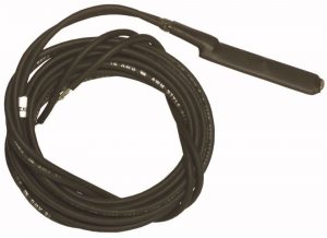

This is a legacy product document supported by Resideo. It is no longer manufactured
APPLICATION
The C7089B Outdoor Sensor is used with the T8500 and T8600 Thermostat families on models with outdoor temperature option. It senses the outdoor temperature for display at the touch of a key. The sensor is encapsulated to protect against water and contaminants, and includes 60 in. leadwires.
SPECIFICATIONS
- Operating Ambient Temperature Range:
-40 to 128°F (-40 to 53°C) - Operating Relative Humidity:
5% to 95% non-condensing - Dimensions in inches (millimeters):
2-1/4 (57) x 3/8 (10) with 60 (1524) leadwires
INSTALLATION
When Installing this Product…
- Read these instructions carefully. Failure to follow them could damage the product or cause a hazardous condition.
- Check the ratings given in the instructions and on the product to make sure the product is suitable for your application.
- Installer must be a trained, experienced service technician.
- After installation is complete, check out product operation as provided in these instructions.

Disconnect power supply before connecting wiring to prevent electrical shock or equipment damage.

Location and Mounting (Fig. 1)
Mount the sensor where:
- setting can not be tampered with.
- there is good air circulation.
- it can measure the true outdoor ambient temperature.
- surface is flat.
- he wire distance between the C7089 and thermostat is less than 200 feet.
Do not mount the sensor:
- in the direct sunlight.
- where hot or cold air blows on the sensor. Discharge line from an outdoor compressor unit, vent or fan will cause inaccurate temperature readings.
- where snow, ice or debris can cover it.
Use the following steps to mount the sensor.
- Remove the sensor from the mounting clip.
- Mark the area on the surface where the C7089B mounting clip will be mounted.
- Mount the clip.
Fig. 1. Typical locations for outdoor sensor.

Wiring
Keep wiring at least one foot away from large inductive loads such as motors, line starters, lighting ballasts, and large power distribution panels. Failure to follow these wiring practices can introduce electrical interference (noise), which can cause erratic system operation. Use shielded cable to reduce interference when rerouting is not possible.
IMPORTANT
Erratic temperature readings from a sensor can occur as a result of any of the wiring practices described below. These practices must be avoided to assure proper operation. Use shielded cable to reduce interference if rerouting of sensor wiring is not possible.
- Do not route temperature sensor wiring with building power wiring, next to control contactors or near light dimming circuits, electric motors or welding equipment.
- Avoid poor wiring connections.
- Avoid intermittent or missing building earth ground.
Disconnect the power supply before connecting the wiring to prevent electrical shock or equipment damage.
Wiring must comply with applicable codes, ordinances and regulations.
- Wire the C7089B Outdoor Sensor to the OT terminals on the thermostat. If the leadwire provided with the C7089B is not long enough, run cable to a hole at the selected C7089B location.
Color-coded, 18-gauge thermostat wire is recommended. For an example of general wiring of the C7089B, see Fig. 2. Pigtail wiring can be used. - Mount the C7089B in its mounting clip.
- Plug wiring hole using non hardening caulk or putty.
T8600 SUBBASE

OF STRUCTURE.


OPERATION
The C7089B Outdoor Sensor converts outdoor ambient temperature to a resistance that the thermostat can interpret. The outdoor temperature is displayed when the Information key is pressed.
NOTE: The thermostat Installer Setup mode number 24 must be set to 01 for the outdoor temperature to be displayed.
The C7089B has a negative temperature coefficient (TC), which means that the resistance increases as the temperature decreases. Fig. 3 shows the resistance characteristics of the C7089B Sensor.
OUTDOOR TEMPERATURE

Fig. 3. C7089B sensor resistance vs. temperature performance characteristics.
CHECKOUT
Allow the C7089B Outdoor Sensor to soak in the outdoor air for a minimum of five minutes before taking a reading.
With an accurate thermometer (±1°F [0.5°C]) measure the temperature at the sensor location, allowing time for the thermometer to stabilize before reading. Press the Information key on the thermostat until the display shows Outdoor followed by the temperature reading. See Fig. 4. The reading should match the reading taken outdoors.
To verify the resistance of the sensor, remove one wire from one of the C7089B wiring terminals. Use an ohmmeter to measure the resistance across the sensor. Then verify sensor accuracy with the temperature/resistance curve of Fig. 3.
Fig. 4. Outdoor temperature display on the thermostat.

CALIBRATION
The C7089B Outdoor Sensor is calibrated at the factory and cannot be recalibrated at the field.
Automation and Control Solutions
Honeywell International Inc.
1985 Douglas Drive North
Golden Valley, MN 55422
Honeywell Limited-Honeywell Limitée
35 Dynamic Drive
Scarborough, Ontario M1V 4Z9