KitchenAid Commercial Style Wall-Mount Canopy Range Hood Owner’s Manual


30″, 36″ AND 48″ (76.2 CM, 91.4 CM, AND 121.9 CM) COMMERCIAL-STYLE WALL-MOUNT CANOPY RANGE HOOD
Installation Instructions and Use & Care Guide
For questions about features, operation/performance, parts, accessories or service, call: 1-800-422-1230
or visit our website at www.kitchenaid.com
In Canada, for assistance, installation and service, call: 1-800-807-6777
or visit our website at www.kitchenaid.ca

IMPORTANT: READ AND SAVE THESE INSTRUCTIONS. FOR RESIDENTIAL USE ONLY.
IMPORTANT : LIRE ET CONSERVER CES INSTRUCTIONS. POUR UTILISATION RÉSIDENTIELLE UNIQUEMENT.
LI3ZAB/W11374532A
RANGE HOOD SAFETY
Your safety and the safety of others are very important.
We have provided many important safety messages in this manual and on your appliance. Always read and obey all safety messages.


All safety messages will tell you what the potential hazard is, tell you how to reduce the chance of injury, and tell you what can happen if the instructions are not followed.
IMPORTANT SAFETY INSTRUCTIONS | |
WARNING: TO REDUCE THE RISK OF FIRE, ELECTRIC SHOCK, OR INJURY TO PERSONS, OBSERVE THE FOLLOWING: |
WARNING: TO REDUCE THE RISK OF A RANGE TOP GREASE FIRE: ■ Never leave surface units unattended at high settings. Boilovers cause smoking and greasy spillovers that may ignite. Heat oils slowly on low or medium settings. ■ Always turn hood ON when cooking at high heat or when flambeing food (i.e. Crepes Suzette, Cherries Jubilee, Peppercorn Beef Flambé). ■ Clean ventilating fans frequently. Grease should not be allowed to accumulate on the fan or filter. ■ Use proper pan size. Always use cookware appropriate for the size of the surface element. WARNING: TO REDUCE THE RISK OF INJURY TO PERSONS IN THE EVENT OF A RANGE TOP GREASE FIRE, OBSERVE THE FOLLOWING: a ■ SMOTHER FLAMES with a close-fitting lid, cookie sheet, or metal tray, then turn off the burner. BE CAREFUL TO PREVENT BURNS. If the flames do not go out immediately, EVACUATE AND CALL THE FIRE DEPARTMENT. ■ NEVER PICK UP A FLAMING PAN – you may be burned. ■ DO NOT USE WATER, including wet dishcloths or towels – a violent steam explosion will result. ■ Use an extinguisher ONLY if: – You know you have a Class ABC extinguisher, and you already know how to operate it. – The fire is small and contained in the area where it started. – The fire department is being called. – You can fight the fire with your back to an exit. a Based on “Kitchen Fire Safety Tips” published by NFPA. ■ WARNING: To reduce the risk of fire or electrical shock, do not use this fan with any solid-state speed control device. |
READ AND SAVE THESE INSTRUCTIONS | |
INSTALLATION REQUIREMENTS | |
Tools and Parts Gather the required tools and parts before starting installation. Read and follow the instructions provided with any tools listed here. | |
| Tools needed ■ Level ■ Drill ■ 1¼” (3 cm) drill bit ■ ¹⁄₈” (3 mm) drill bit if installing into wood ■ ⁵⁄₁₆” (8 mm) drill bit if installing optional backsplash kit ■ ³⁄₁₆” (5 mm) drill bit if installing an in-line blower motor system ■ Pencil |
■ Wire stripper or utility knife ■ Tape measure or ruler ■ Pliers ■ A caulking gun and weatherproof caulking compound ■ Vent clamps ■ Jigsaw or keyhole saw ■ Flat-blade screwdriver ■ Metal snips ■ Phillips screwdriver ■ Scissors |
Parts needed
- Home power supply cable
- 1 – ½” (12.7 mm) UL listed or CSA approved strain3 UL listed wire connectors
- 1 wall or roof cap
- Metal vent system
- Blower motor system – internal or external (see “Blower Motor System” in the “Accessories” section.)
Parts supplied
Remove parts from packages. Check that all parts are included.
- 2 metal grease filters for 30″ (76.2 cm) and 36″ (91.4 cm) models 3 metal grease filters for 48″ (121.9 cm) models
- Range hood canopy with LED lamps installed.
- 1 – 10″ (25.4 cm) square to 10″ (25.4 cm) round duct transition with damper
- Wood support
- Grease drip trays
- 4 – 6 x 80 mm mounting screws
- 4 – 3.5 x 9.5 mm screws
- 6 – 4.2 x 19 mm screws
- 2 – D5.3 x 20 mm washers
- 2 – 10 x 50 mm wall anchors
- T-20 TORX ®† adapter
Location Requirements
IMPORTANT: Observe all governing codes and ordinances. Have a qualified technician install the range hood. It is the installer’s responsibility to comply with installation clearances specified on the model/serial rating plate. The model/serial rating plate is located inside the range hood on the rear wall of the range hood.
Canopy range hood location should be away from strong draft areas, such as windows, doors, and strong heating vents. Cabinet opening dimensions that are shown must be used. Given
dimensions provide minimum clearance. The canopy range hood is factory set for venting through the roof or through the wall.
All openings in the ceiling and wall where the canopy range hood will be installed must be sealed.
For Mobile Home Installations
The installation of this range hood must conform to the Manufactured Home Construction Safety Standards, Title 24 CFR, Part 328 (formerly the Federal Standard for Mobile Home Construction and Safety, Title 24, HUD, Part 280) or when such standard is not applicable, the standard for Manufactured Home Installation 1982 (Manufactured Home Sites, Communities and Setups) ANSI A225.1/NFPA 501A*, or latest edition, or with local codes.
Product Dimensions
Front view

Back view

Optional Full-Width Duct Cover Installations

†®TORX is a registered trademark of Saturn Fasteners, Inc.
Installation Dimensions

| A. For installations with canopy only: 78″ (198.1 cm) minimum above electric cooking surface 84″ (213.4 cm( minimum above the gas cooking surface |
B. For installations with optional duct cover: 90″ (228.6 cm) minimum above electric cooking surface 96″ (243.8 cm) minimum above the gas cooking surface |
IMPORTANT:
Minimum distance “X”: 24″ (61 cm) from electric cooking surfaces
Minimum distance “X”: 30″ (76.2 cm) from gas cooking surfaces
Suggested maximum distance “X”: 36″ (91.4 cm)
Venting Requirements
■ The vent system must terminate to the outdoors.
■ Do not terminate the vent system in an attic or other enclosed area.
■ Do not use 4″ (10.2 cm) laundry-type wall caps.
■ Use metal vent only. A rigid metal vent is recommended. A plastic or metal foil vent is not recommended.
■ The length of the vent system and the number of elbows should be kept to a minimum to provide efficient performance. For the most efficient and quiet operation:
■ Use no more than three 90° elbows.
■ Make sure there is a minimum of 24″ (61.0 cm) of straight vent between the elbows if more than 1 elbow is used.
■ Do not install 2 elbows together.
■ Use clamps to seal all joints in the vent system.
■ The vent system must have a damper. If the roof or wall cap has a damper, do not use the damper supplied with the range hood.
■ Use caulking to seal the exterior wall or roof opening around the cap.
■ The size of the vent should be uniform.
Cold weather installations
An additional back draft damper should be installed to minimize backward cold airflow and a thermal break should be installed to
minimize conduction of outside temperatures as part of the vent system. The damper should be on the cold air side of the thermal
break.
The break should be as close as possible to where the vent system enters the heated portion of the house.
Makeup air
Local building codes may require the use of makeup air systems when using ventilation systems greater than specified CFM of air movement. The specified CFM varies from locale to locale. Consult your HVAC professional for specific requirements in your area.
Venting Methods
Typical Internal Blower Motor System Venting Installations
A 10″ (25.4 cm) round vent system is needed for installation (not included). The hood exhaust opening is 10″ (25.4 cm) round.
NOTE: Flexible vent is not recommended. A flexible vent creates backpressure and air turbulence that greatly reducess
performance.
The vent system can terminate either through the roof or wall.
| Roof Venting A. Roof cap |
Wall Venting A. Wall cap |
Wall Venting A. Wall cap |


Typical In-line Blower Motor System Venting Installations

A. 10″ (25.4 cm) round vent
B. Mount on top of ceiling joists.
C. Roof caps
D. Plywood (optional for some installations)
E. Mount on underside of roof rafters.
F. Mount from cross-members tied to trusses.
G. Duct horizontal; mount to cross-members tied to trusses.
H. Wall cap
Calculating Vent System Length
To calculate the length of the system you need, add the equivalent feet (meters) for each vent piece used in the system.
| Vent Piece | Equivalent Length |
| 45° elbow | 2.5 ft
(0.8 m)
|
| 90° elbow | 5.0 ft
(1.5 m)
|


The maximum equivalent vent lengths are: 10″ (25.4 cm) round vents – 60 ft (18.3 m)
Example vent system

The following example falls within the maximum recommended vent length.
1 – 90° elbow = 5.0 ft (1.5 m)
1 – wall cap = 0.0 ft (0.0 m)
8 ft (2.4 m) straight = 8.0 ft (2.4 m)
Length of system = 13.0 ft (3.9 m)
INSTALLATION INSTRUCTIONS
Prepare Location
■ It is recommended that the vent system be installed before the range hood is installed.
■ If you are installing the optional backsplash, follow the instructions included with that product.
■ Before making cutouts, make sure there is proper clearance within the ceiling or wall for the exhaust vent.
■ Check that all installation parts have been removed from the shipping carton.
- Disconnect power.
- Determine which venting method to use: roof or wall exhaust.
- Select a flat surface for assembling the range hood. Place covering over that surface.
Excessive Weight Hazard
Use two or more people to move and install a range hood.
Failure to do so can result in back or another injury. - Using 2 or more people, lift the range hood onto the covered surface.

Range Hood Mounting Screws Installation
The range hood is attached to the wall with the wood support that is attached to the back of the range hood.
- Determine and mark the centerline on the wall where the canopy range hood will be installed.
- Select a mounting height “X” between a minimum of 24″ (61 cm) from electric cooking surfaces or 30″ (76.2 cm) from gas cooking surfaces, and a suggested maximum of 36″ (91.4 cm), above the cooking surface and the bottom of the range hood and mark a horizontal reference line on the wall.
- Remove the wood support from the back of the range hood by loosening the 2 screws from the inside. Locate and level
the top of the wood support 15³⁄₈” (39.1 cm) above the marked horizontal line and centered on the vertical centerline. Using 2 – 4 of the 6 x 80 mm screws, install wood support so that it is screwed into at least 2 vertical studs.

A. Wood support
B. Bottom of range hood
C. Centerline
D. Dimension “X” = range hood mounting height
NOTE: The screws provided for mounting this range hood must be fastened into solid wood; do not fasten into sheetrock only.
Complete Preparation
- Determine and make all necessary cuts in the wall or roof for the vent system. Install the vent system before installing the
range hood. See the “Venting Requirements” section. - Determine the location where the power supply cable will be run through the wall.
- Drill a 1¹⁄₄” (3.2 cm) hole at this location.
- Pull enough power supply cable through the wall to allow for easy connection to the terminal box.
- Install the 10″ (25.4 cm) square x 10″ (25.4 cm) round vent transition with a damper to the top or rear of the range hood (depending on your installation), using 4 – 3.5 x 9.5 mm screws. Remove the damper from the vent transition when mounting to the rear of the range hood.
NOTE: There is an 8¾” (22.2 cm) flat cover plate mounted on the rear panel of the range hood. It must cover the exhaust
opening in the rear panel of the range hood for top venting or be removed and reinstalled to cover the exhaust opening in
the top panel for rear venting. - Remove terminal box cover and set aside.
- Remove a knockout from the back of the range hood and install a UL listed or CSA approved ¹⁄₂” (1.3 cm) strain relief.
- Place the range hood near its mounting position and run the power supply cable through the strain relief into the terminal box
(enough to make the connection). - Tighten the strain relief screws.
NOTE: Your range hood requires you to purchase either an internal type or an in-line (external type) blower motor system. For internal blower systems, there are blower motor mounting parts in the blower motor installation packet that must be added
to the range hood prior to mounting the range hood to the wall. See the “Install Range Hood Internal Blower Motor” section and the instructions supplied with the blower motor.
Install Range Hood
The range hood attaches to the wall by the 2 mounting screws in the wood support mounted to the wall in the “Range Hood
Mounting Screws Installation” section.
- Using 2 or more people, hang the range hood on the the wall by placing the slotted holes in the range hood back over the
2 screws mounted to the wood support mounted to the wall.
NOTE: If your installation uses the optional duct cover, the vent system needs to be connected to the range hood and
the duct cover mounted to the top of the range hood before tightening the mounting screws. See steps 3 – 5. - Push the range hood up into the narrow slots, align the bottom of the hood to the horizontal line, level the hood, and tighten the 2 mounting screws.
- Mark 2 lower mounting hole center point locations. Drill ¹⁄₈” (0.32 cm) pilot holes if the holes are located into the wood. If holes are not located into the wood, drill two ³⁄₈”(0.95cm) pilot holes and insert 10 x 50 mm wall anchors. Install 2 – 6 x 80 mm screws with D5.3 x 20 mm washers into the lower mounting anchors and tighten.
- Install 4 – 4.2 x 19 mm screws through the back of the hood into the wood support and tighten.
- Connect vent system to the hood. Seal all joints with clamps.
NOTE: If your installation uses the optional full-width duct cover, attach the duct cover to the top of the range hood following the instructions and using the screws that are provided with the duct cover. For information on ordering the optional duct cover, see the “Accessories” section.

Install Range Hood Internal Blower Motor
NOTE: Your range hood requires you to purchase either an internal type or an in-line (external type) blower motor system. See “Blower Motor System” in the “Accessories” section.
The internal blower system can be mounted for top venting or rear venting. For top venting, the mounting bracket and spring clip that comes with the blower system will mount to the top panel of the range hood. For rear venting, the mounting bracket and spring clip that comes with the blower system will mount to the rear panel of the range hood.
Prepare the Internal Blower System
IMPORTANT: Perform steps 1-4 before mounting the range hood.
- Remove grease filters from the range hood. See the “Range Hood Care” section in the Use and Care Guide.
- Install the motor support bracket using three 4.2 x 8 mm screws. Screw bracket to the inside top or back (alternate location on some models), toward the left side of the range hood.
- Install motor spring clip using two 4.2 x 8 mm screws. Screw the spring clip to the inside top or back (alternate location on some models) of the range hood at the proper location for the selected motor system. Slide the mounting tab of the spring clip through the slot in the panel and secure it with the screws. Use the inside set of mounting holes for the single motor system. Use the outside set of mounting holes for the dual motor system.
A. 4.2 x 8 mm screws (3) for the motor support bracket
B. 4.2 x 8 mm screws (2) for a motor spring clip
C. Motor support bracket
D. Motor spring clip (single motor assembly location)
E. Motor spring clip (dual motor assembly location) - Install the 6 mm nuts to the outside top or outside back (alternate location on some models) of the range hood at the proper location for the selected motor system.
■ Two 6 mm nuts are required for the single motor system. Clip nuts into the small square notches located at the left and right end of the square vent opening.
■ Five 6 mm nuts are required for the dual motor system. Clip nuts into the small square notches, one located in the front of the square vent opening and the other four located at the left and right end of the square vent opening.
B. Clip nut locations for single motor assembly (2) - Mount range hood. See the “Install Range Hood” section.


Install Range Hood Internal Blower Motor
- Install the range hood blower motor assembly inside the range hood canopy with the wiring connection to the left for the single motor system and to the front or top for the dual motor system.
Single Blower Motor Assembly
A. Wiring connection
Dual Blower Motor Assembly
A. Wiring connection - Slide the left mounting plate flange under the motor mounting bracket.
B. Mounting plate left flange - Run the power supply wires and connector from the range hood through the hole in the right end of the motor mounting plate.
A. Motor mounting plate hole
B. Power supply wires and connector - Push the right end of the motor mounting plate up and snap it into the spring tab.
NOTE: The spring tab should be outside the slot in the mounting plate.
A. Motor mounting plate
B. Spring clip - Align mounting holes and install 6 x 16 mm screws and 6.4 mm lock washers.
A. Screw with lock washer
B. Mounting hole - Attach power supply connector from the range hood to the connector on the blower motor assembly wiring box.
A. Wiring box connector
B. Power supply connector from the range hood - Go to the “Make Electric Power Supply Connection to Range Hood” section.


Install Range Hood In-Line (External Type)
Blower Motor
NOTE: Your range hood requires you to purchase either an internal type or an in-line (external type) blower motor system.
See “Blower Motor System” in the “Accessories” section.
Prepare for Mounting the In-Line Blower System
The in-line blower system must be fastened to a secure structure of the roof, ceiling, wall, floor, or new or existing frame construction. The 4 holes on either the inlet (bottom) side of the outlet (top) side of the blower must be used to mount the in-line
blower system to the structure.
NOTE: The mounting hole locations must span the studs. Additional stud framing may be required. Plywood may be used
to span open areas between ceiling joists or roof rafters to aid installation. This structure must be strong enough to support the
weight of the in-line blower system (50 lb [22.6 kg] min).
Prepare the In-line Blower System
| Excessive Weight Hazard Use two or more people to move and install in-line blower motor system. Failure to do so can result in back or another injury. |

- Using 2 or more people, move the in-line blower motor system to the mounting location.
- Remove the 10 screws from the front cover of the in-line blower motor housing and set them aside.
- Remove the front cover of the in-line blower motor housing and set it aside.
NOTE: To make the blower motor housing easier to mount, the blower motor assembly can be removed. If you do not want to remove the blower motor assembly, proceed to “Install In-line Blower System” in this section. - Disconnect the motor electrical plug from the blower motor assembly.
- Remove the screws that secure the blower motor assembly to the in-line blower housing and set them aside.
- Pull the spring clip to release the blower motor assembly. Remove the blower motor assembly from the housing and place it on a covered surface.

A. Front cover
B. Blower mounting screws
C. Spring clip
D. Motor electrical plug
Install In-line Blower System
NOTE: The blower motor housing can be mounted using 4 holes from either the inlet side or the outlet side of the blower.

A. Mounting holes
- Position the in-line blower motor housing in its mounting location and mark the 4 mounting hole locations.
- Drill 4 mounting pilot holes using a ³⁄₁₆” (0.48 cm) drill bit.
- Attach the in-line blower motor housing to the mounting location with four 6 x 80 mm mounting screws and washers.
- If it is removed, reinstall the blower motor assembly and secure it with the screws previously removed.
- If it is removed, reattach the motor electrical plug to the connector on the blower motor assembly.
Complete Preparation
- Determine and make all necessary cuts for the vent system.
IMPORTANT: When cutting or drilling into the ceiling or wall, do not damage electrical wiring or other hidden utilities. - Determine the location where the ¹⁄₂” (1.3 cm) wiring conduit will be routed through the ceiling or wall between the in-line blower and the range hood.
- Drill a 1¹⁄₄” (3.2 cm) hole at this location.
- Locate the electrical terminal boxes in the in-line blower housing and range hood (see “Complete Preparation” in the “Prepare Location” section). Remove the terminal box covers and set the covers and screws aside.
A. Electrical terminal box
B. Electrical knockout - Remove the electrical knockout from the in-line blower housing and range hood (see “Complete Preparation” in the “Prepare Location” section) to prepare for the installation of the UL listed or CSA approved ¹⁄₂” (1.3 cm) wiring conduit and conduit connector.
- With the range hood mounted (see the “Install Range Hood” section), run the ¹⁄₂” (1.3 cm) wiring conduit between the inline
blower motor housing and the range hood. Pull enough ¹⁄₂” (1.3 cm) wiring conduit to allow for easy connection to the terminal boxes in the in-line blower housing and range hood. - Run the six 18 AWG wires through the ¹⁄₂” (1.3 cm) wiring conduit and conduit connectors and into the terminal boxes on the in-line blower housing and range hood. Leave enough wire length in each terminal box to make the wiring connections.
- Install the conduit connectors and conduit to the in-line blower housing and range hood electrical terminal boxes.
- Connect the vent system to the range hood and in-line blower system and seal all joints with clamps.

Make Electrical Connections for In-Line Blower Motor System
| Electrical Shock Hazard
Disconnect power before servicing. Replace all parts and panels before operating. Failure to do so can result in death or electrical shock. |


Electrical Connection Inside In-line Blower System
- Disconnect power.
- Connect the wires from the wiring conduit to the wires from the motor electrical plug cable inside the in-line blower housing terminal box.
A. UL listed or CSA approved
¹⁄₂” (1.3 cm) wiring conduit
B. UL listed wire connectors
C. Black wires
D. White wires
E. Red wiresF. B l u e w i r e s
G. Gray wires
H. Green (or yellow/green)
and green/yellow wires
I. Motor electrical plug cable - Use UL listed wire connectors and connect the black wires (C) together.
- Use UL listed wire connectors and connect the white wires (D) together.
- Use UL listed wire connectors and connect the red wires (E) together.
- Use UL listed wire connectors and connect the blue wires (F) together.
- Use UL listed wire connectors and connect the gray wires (G) together.
Electrical Shock Hazard
Disconnect power before servicing.
Replace all parts and panels before operating.
Failure to do so can result in death or electrical shock. - Connect the green (or yellow/green) ground wire to the green/yellow ground wire (H) in the terminal box using UL listed wire connectors.
- Reinstall the in-line blower terminal box cover and screw.
- Reinstall the front cover of the in-line blower housing and secure it with 10 mounting screws.
- With the range, hood-mounted (see the “Install Range Hood” section), locate the wiring cable connector inside the range hood.
- Connect the 6-wire connector assembly supplied with the in-line blower motor system to the mating cable connector from the range hood.
- Locate the terminal box inside the range hood and install a ¹⁄₂” (1.3 cm) UL listed or CSA approved strain relief (see Complete Preparation” in the “Prepare Location” section).
- Run the wire ends from the 6-wire connector assembly through the ¹⁄₂” (1.3 cm) strain relief, leaving enough wire length to make the wiring connections. Tighten the strain relief screws.
- Connect the wires from the 6-wire connector assembly to the wires from the wiring conduit inside the range hood terminal box.
- Connect the same color wires to each other (black to black, white to white, etc.) using UL-listed wire connectors.
NOTE: Connect the green (or green/yellow) ground wire from the wiring conduit to the green (or bare) ground wire from the home power supply using UL listed wire connectors (see the “Make Electrical Power Supply Connections to Range Hood”
section).A. UL listed or CSA approved ¹⁄₂” (1.3 cm) wiring conduit
B. UL listed wire connectors
C. Black wires
D. White wiresE. Red wires
F. B l u e w i r e s
G. Gray wires
H. Green (or green/yellow) wire
I. 6-wire connector assembly - Go to “Make Electrical Power Supply Connection to Range Hood” section.
- Disconnect power.
- Locate terminal box inside of the range hood.
B. Knockout in canopy back into the terminal box
B. Black wires
C. UL listed wire connectors
D. Green, bare or yellow/green wires
E. Home power supply
F. UL listed or CSA approved ¹⁄₂” (1.3 cm) strain relief - Use UL listed wire connectors and connect black wires (B) together.
- Use UL listed wire connectors and connect white wires (A) together.
Electrical Shock Hazard
Disconnect power before servicing.
Replace all parts and panels before operating.
Failure to do so can result in death or electrical shock.
NOTE: When using an in-line blower motor system, the green (or green/yellow) ground wire in the conduit from the In-line blower motor system is to be connected with the green (or bare) wire of the home power supply cable and with the green/yellow wire (D) in the terminal box. - Connect green (or bare) ground wire from the home power supply to the green/yellow ground wire (D) in the terminal box using UL-listed wire connectors.
- Install terminal box cover.
- Check that all light bulbs are secure in their sockets.
- Reconnect power.
- Install grease filters. See “Range Hood Care” section.
- Check operation of the range hood blower and lights. See the “Range Hood Use” section.
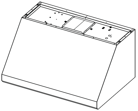
B. LED light switch
C. Blower control switches
D. Grease filter
E. Grease filter handles - If the range hood does not operate, check to see whether a circuit breaker has tripped or a household fuse has blown.
Disconnect the power supply and check that the wiring is correct. - Move the light switch to the “1” position to turn the range hood light to the night light setting.
- Move the light switch to the “2” position to turn the range hood light to a full light setting.
- Move the light switch to the “Off” position to turn the range hood light OFF.
- Move the fan switch to the “On” position to turn the fan ON.
The fan will begin operating at the speed set on the fan speed switch. - Move the fan switch to the “Off” position to turn the fan OFF.

Electrical Connection Inside Range Hood Between In-line Blower System and Range Hood


Make Electrical Power Supply Connection to Range Hood
| Electrical Shock Hazard
Disconnect power before servicing. Replace all parts and panels before operating. Failure to do so can result in death or electrical shock. |


Complete Installation and Check Operation

NOTE: To get the most efficient use from your new range hood, read the “Range Hood Use” section.
Range Hood Controls
Operating the light
Operating the fan
Auto On Fan
The range hood is equipped with a sensor to automatically turn on the fan when excessive heat is detected in the control area.
When the fan switch is in the “Off” position, this sensor will turn the fan to high speed when necessary. When the heat decreases, the fan will turn off.
When the fan switch is in the “On” position, the heat sensor is not active and the range hood functions normally.
Adjusting the fan
The fan has 3-speed controls. Move the fan speed switch to “1” position for low speed, “2” position for medium speed, or “3” position for high speed.
Thermal Protector
The range hood is equipped with a thermal protector to avoid overheating conditions. If the range hood shuts off while in use,
move the fan slider switch to Off to turn off the range hood. Wait approximately 60 minutes, then move the slider to On to restart the range hood.
RANGE HOOD USE
The range hood is designed to remove smoke, cooking vapors, and odors from the cooktop area. For best results, start the hood
before cooking and allow it to operate several minutes after the cooking is complete to clear all smoke and odors from the
kitchen.
The hood controls are located on the underside of the range hood.
