Honeywell ERM5220R Equipment Remote Module Installation Guide
Honeywell ERM5220R Equipment Remote Module Installation Guide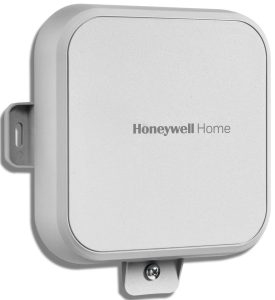

Read these installation instructions completely and follow them carefully.
Installation must be performed by a qualified service technician and must comply with local codes. Disconnect power to all relevant devices before installing or servicing the ERM.
Failure to connect the device according to these instructions may result in damage to the device, the controls, and/or personal injury.

About the ERM5220R
- Wireless RedLink™ communication between condensing unit/ compressor or boiler and thermostat.
- Eliminates the need to run additional wires to your equipment, for example, during a heat pump upgrade.
- Suitable for outdoor use.
- Temperature sensor terminals for outdoor temp sensors or indoor freeze protection.
- LEDs for easy installation checkout.
- May reduce damage to homes since wiring/drilling is eliminated.
NOTE: The ERM5220R is compatible with updated models THX9421R5021, TH8321R1001,
TH8320R1003, and TH8110R1008.
THM5421R1021 EIM is also required with
THX9421R5021. Optional with other models.
Installation Checklist
MATERIALS SUPPLIED

- ERM5220R
- Wall Anchors (x2) and Mounting Screws (x2)
- Extra Cover Screw (optional)
- Installation Instructions
TOOLS NEEDED (NOT SUPPLIED)

- Drill
- Nut Driver Attachment for Drill
- Wire Stripper
- Small Flathead Screwdriver
- Phillips Screwdriver
- 120/240 V to 24 V Transformer (optional)
Terminal Designations

TERMINAL DESIGNATIONS FOR BOILER

INSTALLATION
IMPORTANT
- The ERM is not compatible with RedLink Zone boards.
- To ensure that the ERM will receive a wireless signal at the desired installation location, follow steps 1 to 5 in the Wiring section.
- If your location has metal siding, the ERM’s signal may be affected. If there is no communication or poor signal strength, consider a different location.
- A Prestige (with EIM) or VisionPRO (with or without EIM) will only allow one of the following configurations:
- Enrolled with a single boiler configured ERM;
- Enrolled with a single compressor configured ERM;
- Enrolled with a single boiler configured ERM and enrolled with a single compressor configured ERM.
Wiring
- Make sure power to compressor/boiler is off.
- Remove the front cover by loosening the cover screw and lifting up from the bottom of the ERM.
- Remove 3 to 4 inches of the cable’s outer sheathing, then remove 3/8 to 1/2 inch of insulation from each wire.
- Cable prepared for wiring.
- Cable prepared for wiring.
- For compressor applications: Leave the jumper between terminals J and R in place.
For boiler applications: Remove the jumper between terminals J and R.- Terminal Designations showing the jumper between J and R terminals.
- Terminal Designations showing the jumper between J and R terminals.
- For compressors and boilers: Connect a 24 VAC power source to the R and C terminals on the ERM.
- Connect terminals from the ERM to the appropriate terminals on the compressor/boiler control board.
COMPRESSOR
BOILER
IMPORTANT
If the ERM was previously used with a compressor and will now be used with a boiler:- un-enroll the ERM at the thermostat;
- remove the jumper on the ERM;
- designate Radiant Heat for Heating System Type
(ISU 2000) in your thermostat.
Once power is connected, the “Compressor” (or “Boiler”) LED should illuminate green. (Fig. 9)
OR
- For compressors and boilers:
Put the thermostat in pairing mode.
New thermostat installation: When going through the initial setup the thermostat display will ask “TSTAT CONTROLS AN EQUIP MODULE”.
This refers to an EIM, not an ERM. See note below. The next screen says “connect RedLINK Accessories?” The ERM is an accessory, so select “yes”, and then “next”.
Existing thermostat installation: Select menu – installer options – wireless manager – add device. See thermostat installation guide for assistance. - Once the thermostat is in pairing mode, press and quickly release the “Connect” button on the ERM.
When the ERM is connected to the system, the ERM’s “Connected” LED will be solid green and the thermostat will show “ERM” in its Wireless Manager. (Fig. 10)
OR
Mounting ERM - Use two screws and wall anchors to attach the ERM to the exterior wall near the compressor. The location should be at least 3 feet above ground and oriented with the two wire exits facing downward. See Figs. 11 and 12.
- Attach cover and secure with bottom screw (Fig. 13).


Checkout
Power the system on. Use the thermostat to start a cooling or heating cycle, testing the ERM.
- Restore power to the compressor/boiler as well as your RedLink system.
- Raise/lower the set point on the zone thermostat to initiate a call for heat/cooling.
- Observe all control devices to ensure operation and heat/cooling is active.
- Lower/raise the set point on the thermostat to suspend the call for heat/cooling.
- If outdoor temperature sensor is used, check thermostat to see the readings are active and accurate.
- Be sure to set thermostat to the desired settings when checkout is complete.

TROUBLESHOOTING
NOTE: Disconnect RedLink™ when making changes to the device.
RESET PROCEDURE:
Hold down the “Connect” button on the ERM for 10 seconds. The “Connection” LED should appear red for a few seconds and go out. This indicates the unit is reset.
| Symptom | Possible Cause | Action |
| Relays don’t switch as expected | Incorrect jumper configuration | Check jumper configuration. If incorrect, unenroll from system, change jumper, then re-enroll with system. |
| Connected LED is red | Loss of communication with system | Verify thermostat and/or Equipment Interface Module are powered and functioning correctly. |
| Connected LED is off | Device is not enrolled with system | Enroll with system. |
| No LEDs are on | No power to device | Verify 24 VAC at R/C terminals. |
| No outdoor temperature shown on thermostat | No wired outdoor temperature sensor connected to ERM, or device configured as boiler | Connect outdoor temperature sensor to S1/S1 terminals. Device only reports outdoor temperature temperature when configured as compressor. |
| Thermostat shows “—” for outdoor temperature | Wired outdoor temperature sensor failed | Check sensor for short circuit or open circuit. |
| Outdoor temperature reading at thermostat is too high | Sun load on sensor | Verify outdoor temperature sensor is not in direct sunlight. May need to use longer wire to mount in ideal location. |
| Compressor doesn’t turn on, “Y” LED is blinking | 5-minute compressor lockout after power cycle | Wait 5 minutes, compressor will turn on after safety timeout. |
| Emergency backup control doesn’t function (if configured as boiler) | No valid indoor temperature sensor | Check sensor for short circuit or open circuit, or install indoor temperature sensor on S1/S1 terminals. |
SPECIFICATIONS
Operating Ambient Temperature Range:
Compressor: -40 to +155 ºF (-40 to +68 ºC)
Boiler: 30 to +130 ºF (-1 to +54 ºC)
Operating Relative Humidity Range: 0 – 99 %
Electrical: 24 VAC, 50/60 Hz.
Dimensions: 175 mm x 168 mm x 38 mm
Wireless capability via RedLink™ technology

SEPARABLE PARTS
ERM with TH8321R1001/U: YERM5220R8321
ERM with TH8321R1001/U and THM5421R1021: YERM5220RVPEIM
FCC REGULATIONS
§ 15.19 (A)(3)
This device complies with part 15 of the FCC Rules. Operation is subject to the following two conditions:
- This device may not cause harmful interference, and
- this device must accept any interference received, including interference that may cause undesired operation.
IC REGULATIONS
RSS-GEN
This device complies with Industry Canada’s licence-exempt RSSs.
Operation is subject to the following two conditions:
- This device may not cause interference; and
- This device must accept any interference, including interference that may cause undesired operation of the device.
FCC WARNING
(§15.21) (USA ONLY)
Changes or modifications not expressly approved by the party responsible for compliance could void the user’s authority to operate the equipment.
5 YEAR WARRANTY
Resideo warrants this product, excluding battery, to be free from defects in workmanship or materials, under normal use and service, for a period of five (5) years from the date of first purchase by the original purchaser. If at any time during the warranty period the product is determined to be defective due to workmanship or materials, Resideo shall repair or replace it (at Resideo’s option).
If the product is defective, (i) return it, with a bill of sale or other dated proof of purchase, to the place from which you purchased it; or (ii) call Resideo Customer Care at 1-800-633-3991. Customer Care will make the determination whether the product should be returned to the following address: Resideo Return Goods, 1985 Douglas Dr. N., Golden Valley, MN 55422, or whether a replacement product can be sent to you.
This warranty does not cover removal or reinstallation costs. This warranty shall not apply if it is shown by Resideo that the defect was caused by damage which occurred while the product was in the possession of a consumer.
Resideo’s sole responsibility shall be to repair or replace the product within the terms stated above. RESIDEO SHALL NOT BE LIABLE FOR ANY LOSS OR DAMAGE OF ANY KIND, INCLUDING ANY INCIDENTAL OR CONSEQUENTIAL DAMAGES RESULTING, DIRECTLY OR INDIRECTLY, FROM ANY BREACH OF ANY WARRANTY, EXPRESS OR IMPLIED, OR ANY OTHER FAILURE OF THIS PRODUCT.
Some states do not allow the exclusion or limitation of incidental or consequential damages, so this limitation may not apply to you.
THIS WARRANTY IS THE ONLY EXPRESS WARRANTY RESIDEO MAKES ON THIS PRODUCT. THE DURATION OF ANY IMPLIED WARRANTIES, INCLUDING THE WARRANTIES OF MERCHANTABILITY AND FITNESS FOR A PARTICULAR PURPOSE, IS HEREBY LIMITED TO THE FIVE YEAR DURATION OF THIS WARRANTY. Some states do not allow limitations on how long an implied warranty lasts, so the above limitation may not apply to you.
This warranty gives you specific legal rights, and you may have other rights which vary from state to state. If you have any questions concerning this warranty, please write Resideo Customer Care, 1985 Douglas Dr, Golden Valley, MN 55422 or call 1-800-633-3991.

Resideo Technologies, Inc.
1985 Douglas Drive North, Golden Valley, MN 55422
1-800-468-1502
33-00135EFS—09 M.S. Rev. 02-20 | Printed in United States
© 2020 Resideo Technologies, Inc. All rights reserved.
The Honeywell Home trademark is used under license from Honeywell International, Inc.
This product is manufactured by Resideo Technologies, Inc. and its affiliates.