Honeywell 27826-1034574 Vi-Go Vertical
Lifeline System Instruction Manual
Honeywell 27826-1034574 Vi-Go Vertical Lifeline System Instruction Manual

Thank You
Thank you for your purchase of Miller fall protection equipment manufactured by Honeywell Safety Products. Miller brand products are produced to meet the highest standards of quality at our ISO 9001 certified facility Miller equipment will provide you with years of use when cared for properly.

All persons using this equipment must read, understand and follow all instructions. Failure to do so may result in serious injury or death. Do not use this equipment unless you are properly trained.

Questions? CALL 1.800.873.5242
It is crucial that the authorized person/user of this equipment read and understand these instructions. In addition, federal law requires employers to ensure that all users are trained in the proper installation, use, inspection, and maintenance of fall protection equipment. Fall protection training should be an integral part of a comprehensive safety program. Proper use of fall arrest systems can save lives and reduce the potential of serious injuries from a fall. The user must be aware that forces experienced during the arrest of a fall or prolonged suspension may cause bodily injury. Consult a physician if there is any question about the user’s ability to use this product. Pregnant women and minor children must not use this product.
1.0 Purpose
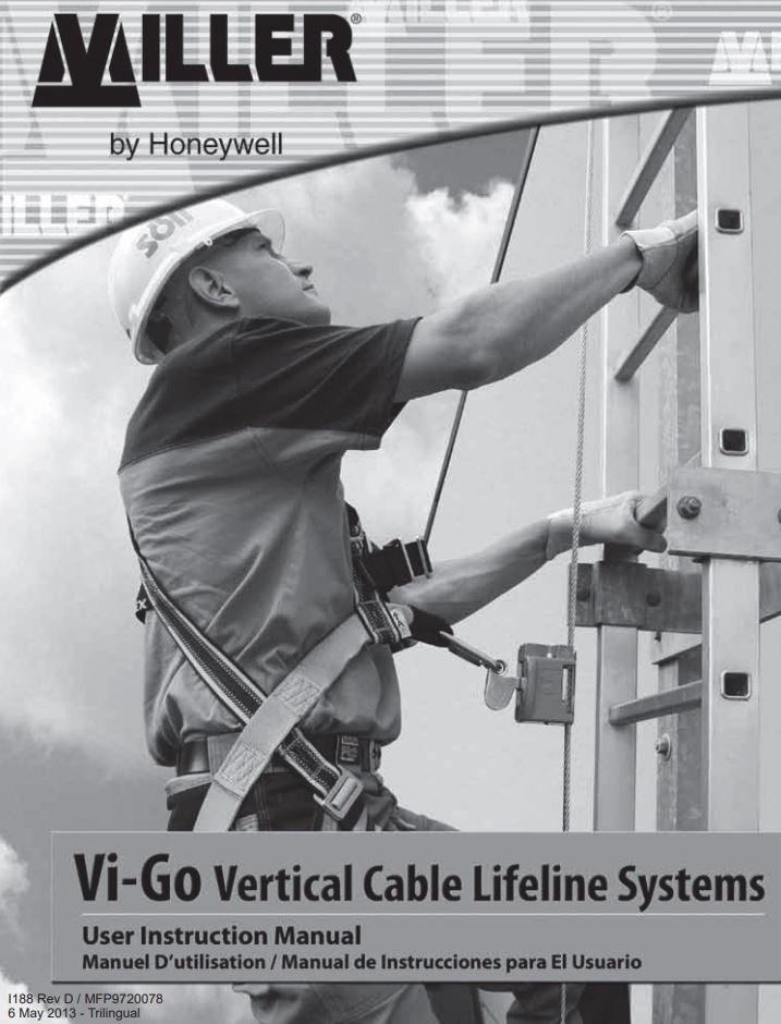
Vi-Go Vertical Cable Lifeline Systems are innovative climbing and fall arrest systems that provide superior fall SURWHFWLRQIRU¿[HGODGGHUDSSOLFDWLRQV
2.0 General Requirements, Warnings and Limitations
2.1 General Fall Protection Warnings
All warnings and instructions shall be provided to authorized persons/users. Warnings and instructions must be read and understood prior to using this equipment.
All authorized persons/users must reference the regulations governing occupational safety, as well as applicable standards (i.e, ANSI or CSA). Refer to SURGXFWODEHOLQJIRULQIRUPDWLRQRQVSHFL¿F26+$ regulations, and ANSI and CSA standards met by this system.
Proper precautions should always be taken to remove any obstructions, debris, material, or other recognized hazards from the work area that could cause injuries or interfere with the operation of the system.
All equipment must be inspected before each use according to the manufacturer’s instructions.
All equipment should be inspected by a qualified person on a regular basis.
To minimize the potential for accidental disengagement, a competent person must ensure system compatibility.
Equipment must not be altered in any way. Repairs must be performed only by the equipment manufacturer, or persons or entities authorized, in writing, by the manufacturer.
Any product exhibiting deformities, unusual wear, or deterioration must be immediately discarded.
Do not use if the unit or any part of the system appears to be damaged. Any equipment subject to a fall must be removed from service.
The user shall have a rescue plan and the means at hand to implement it when using this equipment. Never use fall protection equipment for purposes other than those for which it was designed. Fall protection equipment should never be used for towing or hoisting. Never remove product labels, which include important warnings and information for the authorized person/user.
2.2 System Warnings and Limitations
System Compatibility
Vi-Go Vertical Cable Lifeline Systems are designed for use with Honeywell-approved components. Substitution or replacement with non-approved component combinations, sub-systems, or both, may affect or interfere with the safe function of each other and endanger the compatibility within the system. This incompatibility may affect the reliability and safety of the total system. Vi-Go Systems must be used in conjunction with a Vi-Go Cable Sleeve with auto-locking carabiner (or other Honeywell-approved connector) and a Miller full-body harness equipped with a front attachment point designated for ladder climbing. [NOTE: All instructions and warnings provided with the cable sleeve, connector and harness must be read and understood before using the equipment.]
System Capacity
A maximum of four users may simultaneously be connected to a Vi-Go Vertical Cable Lifeline System so long as the load-bearing capacity of the base structure is adequate. For Vi-Go Systems using the 10 ft. (3m) top bracket assembly, the number of users is limited to two. The distance between users must not be less than 5-1/4 ft. (1.6m) to ensure that, in the event of a fall, the person falling will not strike a user below. (Note: According to ANSI A14.3, only one worker may be on the system between cable guides.)
Fall Clearance
Ensure that adequate clearance exists in the fall path to avoid striking a lower level, some other object, or another user.
Environmental Hazards
Use of this equipment in areas where environmental hazards exist may require additional precautions to limit the possibility of injury to the user or damage to the equipment. Hazards may include, but are not limited to, extreme temperatures, caustic chemicals, corrosive environments, high voltage power lines, explosive or toxic gases, moving machinery, and sharp edges. Do not expose the equipment to any hazard which it is not designed to withstand. Consult the manufacturer in cases of doubt.
- Ensure that the system is free of grease, oil and ice.
- Cable lifeline must be Kept clean.
- Use of this system is not suitable when the user is positioned on an unstable surface, fine-grain material, or particulate.
3.0 System Requirements
Before installation of Vi-Go system, the structure or ladder on which the system is to be affixed must be certified to be capable of withstanding the potential loads that may be applied in the event of a fall arrest and must meet the specified ladder requirements.
Ladder Requirements
A ladder must to ANSI A14.3, the minimum width of the ladder should be 18 inches from inside rail to inside rail.
A system may be attached to square, diamond or L-shaped (angle iron) rungs so long as the rungs meet the minimum 3/4 inch and maximum 1-1/8 inches outer diameter requirements. A spacer may be required for angle iron installations. Please contact Honeywell Technical Service at 800-873-5242 for additional information and installation assistance.
Top Bracket
Connection loads include system pretension and forces generated by arresting a fall. The load requirements vary due to number of users on the system and installation to the structure (i.e., number of rung clamp assemblies used).
For calculation purposes in determining the load each ladder rung must be able to withstand, assume the maximum load on each bracket is distributed evenly throughout the number of top bracket rung clamp assemblies. [Example: Based on a single-user system with the top bracket installed with three rung connections, the assumed load for each rung would be 1,100 lbs. (3,300/3).] An additional top bracket rung clamp assembly can be purchased separately and used to spread the load requirements over four (4) rungs rather than three (3). [Example: For a system with two (2) users the loads transmitted to each rung is reduced from 1,267 lbs. (3,800/3) to 950 lbs. (3,800/4).]

Bottom Bracket
The bottom bracket connection must be capable of supporting a system load of 750 lbs. in the direction of loading.
4.0 System Diagrams and Description of Components
4 .1 V i-Go AU TOM AT I C PASSTHROUGH System


4 .2 V i-Go M AN UAL PASSTHROUGH System


4.3 System Replacement Parts

5.0 System Installation

5.1 Installation of Top Bracket Assembly
The top bracket assembly may be installed to extend above the ladder to allow workers to step safety onto the platform without disconnecting from the lifeline. It is recommended to be mounted at the center of the ladder for ease of use and access, but can be installed toward the side of the ladder if required.
For typical installation of the 5 ft. (1.5m) top bracket assembly, refer to Figure 1a. This installation to four (4) users simultaneously. The 7 ft. (2m) and 10 ft. (3m) top bracket assemblies are installed as shown in Figure 1b. [Note: All systems using the 10 ft. (3m) top bracket assembly are limited to two (2) users. An extra rung clamp assembly may be used in the installation of the top bracket to lower the loads transmitted to each ladder rung (see Fig. 1c).
For systems limited to one (1) user, the 5 ft. (1.5m) top bracket may be installed with two rung clamp assemblies (see Fig. 1d). Ensure the ladder will withstand the loads between the two rungs.


1. Place the top bracket against the rungs of the ladder at the desired height (see either Fig. 1a or 1b). Install For 5 ft. (1.5m) bracket: Place U-bolt around the rung of the ladder and through the holes provided at the bottom of the bracket. For 7 ft. (2m) or 10 ft. (3m) bracket: Place bolts through the holes provided at the bottom of the bracket and through mounting plate on opposite side of ladder rung as shown. Install washers and torque fasteners to 20 plus or minus 2 ft. lbs.
WARNING: The bottom U-clamp must be installed correctly or the bracket may slip under load.
2. Continue to hold bracket against the rungs of the ladder. Install rung clamp assembly by placing U-bolts around the rung of the ladder and inserting through the mounting plate. Install washers and torque fasteners to 20 plus or minus 2 ft. lbs. Repeat procedure for remaining rung clamp assemblies.
5.2 Installation of Cable to Top Bracket Assembly
Use only Honeywell-approved cable . Inspect cable before installation. Do not install damaged cable. Safety glasses and gloves should be worn when handling cable.
When cutting the cable on site during the installation procedure is preferred or necessary, refer to 5.6 Options for Terminating Cable in the Field. WARNING: All instructions and warnings provided with the cable termination fittings must be read and understood before using the equipment.
- Install quick link to cable thimble (see Fig. 2).
- Then connect quick link with cable to the shackle on the underside of the inline shock absorber. Cotter Tighten quick link until snug. Do not use if quick Pin link does not close and tighten.

Note: Ensure the cotter pin is through the shackle bolt and bent over so that it will not back out Do Not use systme if cotter pin is MISSING.
5.3 Installation of Intermediate Cable Guides

Intermediate Cable Guides are designed to keep the climber from excessively defection the cable and to protect the cable form chafing against the ladder or structure. cable guides should be placed at 25 ft. (7.6m) minimum to 40 ft. (12.2m) maximum intervals along the cable from the top bracket to the bottom bracket. Cable guides may be placed at any point along the cable that may come in contact with the ladder or structure. For installations in situations of vibration or high wind, consideration should be given to placing the intermediates closer together.
AUTOMATIC Pass-Through Cable Guides
- Place intermediate cable guide against ladder rung (see Fig. 3).
- Install U-bolt around ladder rung and through holes provided in guide as shown.
- Install washers and torque fasteners to 20 plus or minus 2 ft. lbs.
MANUAL Pass-Through Cable Guides
Typical Installation
- Place cable guide on top of ladder rung (see Fig. 4a). 2
- Install U-bolt around underside of ladder rung and through holes provided in cable guide.
- Install washers and torque fasteners to 20 plus or minus 2 ft. lbs.

90 Degree Installation Note: High wind areas permit rotating the end of this cable guide 90 degrees in either direction. When installation requires this option, cable guides should be alternated from left to right throughout the length of the system.
- Remove fasteners from cable guide end.
- Rotate end 90 degrees and reinsert fasteners (see Fig. 4b).
- Torque fasteners to 20 plus or minus 2 ft. lbs.
- To install cable guide with 90 degree end, follow above procedure except insert U-bolt through the two holes furthest from the cable end on the guide bracket.


5.4 Installation of Bottom Bracket Assembly
WARNING: Inspect the bottom bracket assembly. Do not use if there are any damaged or missing components. Missing, damaged or omitted components can result in the bracket slipping under a load.
- Place bottom bracket against the rungs of the ladder at the desired location aligning the bracket so that the ladder rung is centered between the two vertically placed holes in the bottom of the bracket. (see Fig. 5).
- Install bolts through holes in bottom of bracket and through plate on opposite side, including washers, as shown. Torque fasteners to 20 plus or minus 2 ft. lbs.
- Install U-bolts around ladder rung at top of bracket and through mounting plate. Install washers and torque fasteners to 20 plus or minus 2 ft. lbs.

5.5 Installation of Cable and Tensioning Assembly to Bottom Bracket Assembly

- Install saddle clips loosely around cable attached to tension rod (see Fig. 6).
- Slide the tension rod down the cable and through the hole in the bottom bracket until a sufficient amount of threads are through to install the compression spring, washer and tensioning nut.
- Remove excess cable by pulling cable through the saddle clips. Tighten and torque saddle clips to 40 to 45 ft. lbs.
- Tighten tensioning nut until cable is taut. Compress spring until the distance of 5-1/2* is achieved. Do not completely compress spring. if an sufficient amount of threads are exposed repeat procedure from Step 3.
- When proper tensioning of cable is achieved, install jam nut against tensioning nut.
- Discard excess cable by cutting below the lower doddle clip, living approximately 3″ of cable below the lower saddle clip.


5.6 Options for Terminating Cable in the Field
Options are available for increased versatility during installation to accommodate variable cable lengths. These options are compatible with 3/8″ diameter approved cable only.

Thimble and Wire Rope Cable Termination Kit (VGTWC)
- Feed cable around cable thimble, turning back 5-1/4″ of cable from thimble end. Install first cable clip one clip base width (1-1/8*) from dead end of rope. Use torque wrench to tighten evenly, alternating from one nut to the other until reaching a torque of 45 ft. lbs.
- Install second cable clip as close to the thimble as possible. Again, use torque wrench to tighten evenly to 45 ft. lbs.

Fast-Attach Fitting for 3/8” Diameter Approved Cable (VGF-1)

5 .7 Optional V I-Go Anchorage Connector

V i-Go Anchorage Connector
The Vi-Go Anchorage Connector is designed to provide a convenient tie-off point for workers when entering/exiting at the top of Vi-Go Vertical Cable Lifeline Systems. The Vi-Go Anchorage Connector is designed for one person only with a capacity of 310 lbs. (140.6kg).

WARNING: All instructions and warnings provided with the anchorage connector must be read and understood before using the equipment.
6.0 System Operation
- Don a Miller full-body harness according to the manufacturer’s instructions.
- Install the Vi-Go Cable Sleeve to the vertical cable lifeline according to the manufacturer’s instructions.
- Attach the cable sleeve to the front attachment point, designated for ladder climbing, of the full-body harness using a Miller approved auto-locking carabiner or other Miller approved connector.
- Verify that the carabiner (or connector) keeper/gate is closed and locked.
- Ascend and descend the ladder passing intermediate cable guides per the manufacturer’s instructions supplied with the cable sleeve.
7.0 Training
It is the responsibility of the user and the purchaser of this equipment to assure they are familiar with these instructions and are trained in the proper use, installation, operation, inspection, maintenance and limitations of this product. Training should be conducted periodically and without exposing the trainee to a fall hazard. Training is an integral part of our Total Solution in fall protection, since no fall protection equipment regardless of how effective can save an employee who is not trained in its use. To meet this crucial requirement, Miller Training provides the knowledge and skills necessary to achieve a safe, more productive work environment. For more information on Miller Training, contact a representative today: 800.873.5242.
8.0 Inspection and Maintenance
Inspection
The Vi-Go System is designed for today’s rugged work environments. To maintain its service life and high performance, all components should be inspected frequently. Visually inspect before each use. Regular inspection by a competent person for wear, damage or corrosion should be a part of your safety program. Replace equipment if any of the defective conditions explained in this manual are found.
System Inspection
Before each use, visually inspect for the following:
- Inspect all components for physical damages, cracks, wear and corrosion.
- Check fasteners, bolts and pins for damages, cracks, wear and corrosion.
- Inspect the cable lifeline for cuts, frays, kinks, broken strands or other signs of unusual wearing patterns.
(CAUTION: Always wear gloves when inspecting wire repel) - Check cable tension ensuring there is no slack. Retention cable to specifications as per section 5.6 of this manual.
- Inspect for malfunctioning components, broken or missing springs and fasteners. [For replacement parts call: 800.873.5242]
- Inspect cable sleeve, connector and full-body harness according to the manufacturer’s instructions.
Cleaning and Storage
Basic care of all Miller fall protection equipment will prolong the life of the unit and will contribute toward the performance of its vital safety function. Proper storage and maintenance after use are as important as cleansing the equipment of dirt, corrosives, or contaminants. Clean system components using a cloth dampened with water and mild soap or detergent and towel dry. Storage areas should be clean, dry and free of exposure to fumes or corrosive elements.
Servicing
Servicing must only be carried out by a qualified person trained in the inspection and replacement of the system. A record log of all servicing and inspection dates for this system must be maintained. This system and all its components and devices must be withdrawn from service if subjected to fall arresting forces. Only original Miller fall protection replacement parts are approved for use in this system. Contact Honeywell Technical Service at 800.873.5242 if you have any questions.
Product Labels

Inspection and Maintenance Log
Register Inspection et D’entretien
DATE OF MANUFACTURE: _________________________________________________
MODEL NUMBER:________________________________________________________
DATE PURCHASED: ______________________________________________________

Notes

MILLER®)FALL PROTECTION PRODUCTS TOTAL SATISFACTION ASSURANCE
At Honeywell Safety Products and its predecessors, we have been providing quality Miller brand fall protection equipment to millions of workers worldwide since 1945.
LIMITED LIFETIME WARRANTY
BACKED BY OVER 65 YEARS IN THE FALL PROTECTION BUSINESS We sincerely believe that our fall protection equipment is the best in the world. Our products endure rigorous tests to ensure that the fall protection equipment you trust is manufactured to the highest standards. Miller fall protection products are tested to withstand normal wear and tear, but are not indestructible and can be damaged by misuse.
Our Limited Lifetime Warranty does not apply to normal wear and tear or abusive treatment of the product. In the unlikely event that you should discover defects in either workmanship or materials, under our Limited Lifetime Warranty, we will repair or replace the product at our expense. If a replacement is necessary and your product is no longer available, a comparable product will be substituted. Should a product issue surface, contact us at 800.873.5242.

Toll Free: 800.873.5242 Fax: 800.892.4078
Download this manual at: www.millerfallprotection.com
Honeywell Safety Products
P.O. Box 271, 1345 15th Street
Franklin, PA 16323 USA