Honeywell CFLCMK Miller Cab Mount Bracket Instruction Manual

USER Instruction Manual


All persons using this equipment must read, understand and follow all instructions. Instructions supplied with the self-retracting lifeline/fall limiter at the time of shipment must also be followed. Failure to do so may result in serious injury or death. Do not use this equipment unless you are properly trained.

Purpose
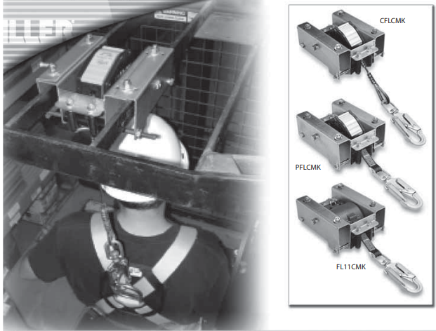
The Miller Cab Mount Bracket (CMB) is a wide range of lift truck cabs. Adjustable side plates allow the bracket to accommodate cab bars or guard stringers from 3-3/4″ (9.5cm) to 9-1/8″ (23cm). The bracket is constructed of heavy-duty, zinc-plated steel for greater durability and longer service life. The Cab Mount Bracket must be used in conjunction with a Miller MiniLite® Fall Limiter (FL11), Miller Scorpion™ Personal Fall Limiter (PFL), or Miller Black Rhino™ Self-Retracting Lifeline (CFL).
General Requirements, Warnings, and Limitations
All warnings and instructions shall be provided to authorized persons/users.
All authorized persons/users must reference the regulations governing occupational safety as well as applicable ANSI or CSA standards.
Proper precautions should always be taken to remove any obstructions, debris, material, or other recognized hazards from the work area that could cause injuries or interfere with the operation of the system.
All equipment must be inspected before each use according to the manufacturer’s instructions. the person on a regular basis.
To minimize the potential for accidental disengagement, a competent person must ensure system compatibility.
All Miller fall protection products are designed for use with Miller-approved components.
Substitution or replacement with non-approved component combinations or subsystems or both may affect or interfere with the safe function of each other and endanger the compatibility within the system. This incompatibility may affect the reliability and safety of the total system.
Equipment must not be altered in any way.
Repairs must be performed only by the manufacturer, or persons or entities authorized in writing by the manufacturer.
Any product exhibiting deformities, unusual wear, or deterioration must be immediately discarded. Any equipment subject to a fall must be removed from service.
The authorized person/user shall have a rescue plan and the means at hand to implement it when using this equipment.
Never use fall protection equipment for purposes other than those for which it was designed.
Equipment must not be exposed to environmental hazards and chemicals which may produce a harmful effect.
Use in a corrosive or caustic environment dictates a more frequent inspection and servicing program to ensure the integrity of the product is maintained.
Do not allow equipment to come in contact with anything that will damage it including, but not limited to, sharp, abrasive, rough or high-temperature surfaces, welding, heat sources, electrical hazards, or moving machinery.
Do not expose the equipment to any hazard which it is not designed to withstand. Consult the manufacturer in cases of doubt.
Always check for obstructions below the work area to make sure the potential fall path is clear.
Allow adequate fall clearance below the work surface.
Never remove product labels, which include important warnings and information for the authorized person/user.
Installation
Before installation of any anchorage connector, carefully inspect to ensure that it is in useable condition. Refer to the inspection section of this manual.
Only trained and competent personnel should install and use this equipment.
Fall arrest systems used with the anchorage connector must be rigged in accordance to regulatory requirements. [All instructions and warnings provided with the components of the personal fall arrest system must be read, understood, and followed.]
Make sure that all connections within the fall arrest system are compatible.
The Cab Mount Bracket must be used with an approved Miller self-retracting lifeline/fall limiter and is designed FOR USE BY ONE PERSON ONLY. The maximum capacity is 310 lbs. (140.6kg).
The Cab Mount Bracket has a minimum tensile strength of 5,000 lbs. (22.2kN).
The anchorage that this product is attached to must be capable of supporting 5,000 lbs. (22.2 kN) per part of a complete personal fall arrest system which maintains a safety factor of at least two.
Anchorage requirements based on ANSI are as follows:
must be multiplied by the number of personal fall arrest systems attached to the anchorage.
The Cab Mount Bracket meets OSHA and ANSI A10.32.
IMPORTANT : Figure 1 Drawing is provided for identification of parts and as an installation reference showing how a Miller self-retracting lifeline or fall limiter is installed in the bracket and the bracket to the cab bars. Each self-retracting lifeline/fall limiter, however, has slightly different installation instructions. Please follow closely the installation instructions for your particular model with regard to differences in roller positioning on the cab mount bracket

| 1 | Side Plate |
| 2 | Clevis Pin |
| 3 | Cotter Pin |
| 4 | Adjustment Bolts |
| 5 | Set Screws |
| 6 | Bottom Bolt |
| 7 | Roller |
| 8 | Bottom Bolt Nut |
| 9 | Back Bracket Bolt |

Installing MiniLite Fall Limiter (FL11) or Scorpion Personal Fall Limiter (PFL) to Cab Mount Bracket / Installing Cab Mount Bracket to Cab Bars
- Remove the bottom bolt and side plates. (Ref. Fig. 2 & 3)
- Insert FL11 or PFL unit. (Ref. Fig. 1).
NOTE (applies to FL11 only): The side of the unit where the webbing exits the housing must be closest to the bottom of the bracket.
Install clevis pin (Item 2 of Fig. 1). Clevis pin must pass through the top bracket plate, anchorage ring on the fall limiter, and bottom bracket plate. Install cotter pin (Item 3 of Fig. 1) completely through clevis pin.
WARNING: Cotter pin must be installed to ensure the unit remains in the bracket in the event a fall. - Position plastic roller between upper roller holes and insert 3/8″ -16 x 4″ bolt through upper roller positioning holes and plastic roller. Tighten nut. (Ref. Fig. 2 & 4a)
NOTE: The webbing lifeline should be positioned below the upper roller. - Re-install side plates, but do not completely tighten adjustment bolts (Item 4 of Fig. 1).
- Install cab mount bracket to cab bars by loosening adjustment bolts as necessary and positioning bracket until it fits over both cab bars. Slide the unit to the desired location and tighten set screws (Item 5 of Fig. 1).
- Position a second plastic roller between lower roller holes and insert long bottom bolt completely
through side plate holes, lower roller positioning holes, and plastic roller. Tighten nut. (Ref. Fig. 4b) NOTE: For cab bars with a span of 7″ or larger, use the 10″ long bolt provided.
NOTE: The webbing lifeline must be positioned between the rollers with the warning flag fall indicator outside of the rollers. - Install the remaining bolt (Item 9 of Fig. 1) at the back of the bracket and tighten the nut.
- Tighten all adjustment bolts (Item 4 of Fig. 1) until snug.


Installing Black Rhino Self-Retracting Lifeline (CFL) to Cab Mount Bracket / Installing Cab Mount Bracket to Cab Bars
- Remove the bottom bolt and side plates. (Ref. Fig. 2 & 3)
- Insert CFL unit (Ref. Fig. 1 & 5a) and install clevis pin (Item 2 of Fig.
1). Clevis pin must pass through the top bracket plate, anchorage ring on the self-retracting lifeline, and bottom bracket plate. Install cotter pin (Item 3 of Fig. 1) completely through clevis pin.
WARNING: Cotter pin must be installed to ensure the unit remains in the bracket in the event a fall. - Position plastic roller between upper roller holes and insert 3/8″ -16 x 4″ bolt through upper roller positioning holes and plastic roller. Tighten nut.
(Ref. Fig. 2 & 5b)
NOTE: The cable lifeline must be positioned above the roller. - Re-install side plates, but do not completely tighten adjustment bolts (Item 4 of Fig. 1).
- Install cab mount bracket to cab bars by loosening adjustment bolts as necessary cab bars. Slide the unit to the desired location and tighten set screws (Item 5 of Fig. 1).
- Install long bottom bolt (Item 6 of Fig. 1) and tighten nut (Item 8 of Fig. 1). (Ref. Fig. 5c)
NOTE: For cab bars with a span of 7” or larger, use the 10″ long bolt provided.
NOTE: The webbing lifeline must be positioned between the rollers with the warning flag fall indicator outside of the rollers. - Install the remaining bolt (Item 9 of Fig. 1) at the back of the bracket and tighten the nut.
- Tighten all adjustment bolts (Item 4 of Fig. 1) until snug.


Inspection and Maintenance
Inspection
Miller products are designed for today’s rugged work environments. To maintain their service life and high performance, all components should be inspected frequently. The cab mount bracket must be visually inspected by the user before each use and inspected by a Competent Person on a regular basis. Do not use if any of the following conditions are detected.
Inspect product for any of the following: bent, cracked, distorted, worn, malfunctioning or damaged parts; loose fasteners or missing parts/components; deterioration or excessive wear; deformation; corrosion; signs that indicate the product has been subjected to a fall arrest; or any other indications of damage/problems that may affect the integrity and operation of the product. Inspect the cotter pin to be sure that it is in usable condition and will stay installed to the clevis pin. Inspect self-retracting lifeline/ fall limiter according to the instructions supplied with the unit. If in doubt, contact the manufacturer.
Devices that do not pass inspection or have been subjected to fall arresting forces must be removed from service.
Cleaning and Storage
Basic care of all Miller Fall Protection equipment will prolong the life of the unit and will contribute toward the performance of its vital safety function. Periodically clean the device using a damp cloth and mild detergent to remove any dirt, paint, corrosives, contaminants, or other materials that may have accumulated. When not in use, store in a clean, dry area, free of exposure to fumes or corrosive elements.
Servicing
Servicing of Miller Fall Protection equipment must only be carried out by Miller Fall Protection or persons or entities authorized in writing by Miller Fall Protection. A record log of all servicing and inspection dates for this device must be maintained. Only original Miller replacement parts are approved for use in this device. Non-repairable devices that do not pass an inspection must be disposed of in a manner to prevent inadvertent further use. Contact Miller Technical Services at 800.873.5242 if you have any questions.

CAB MOUNT BRACKET
Model:
WARNING
The manufacturer’s instructions supplied with this product at the time of shipment must be followed. Failure to do so may result in serious
injury or death. Contact Miller Fall Protection if an instruction manual is needed.
ADVERTISEMENT
Vous devez respecter les instructions du fabricant que vous avez recues avec le produit. Dans le cas contraire, vous risquez des blessures graves ou meme lamort. Contactez Miller Fall Protection si vous avez besoin d’un noveau manual.
Questions? Call: 800/873-5242
Toll-Free: 800.873.5242
Fax: 800.892.4078
Download this manual at:
www.millerfallprotection.com
Honeywell Safety Products P.O. Box 271, 1345 15th Street Franklin, PA 16323 USA