Honeywell IAQPoint2 Gas Monitor User Guide


IAQPoint2 Gas Monitor
Quick Start Guide
Introduction
The IAQPoint2 indoor air quality monitor features a simple-to-use, customizable touchscreen display along with triple monitoring of indoor air quality parameters (carbon dioxide or volatile organic compounds, plus temperature and humidity) and demand-controlled ventilation. The IAQPoint2 monitor increases energy efficiency in commercial buildings by triggering fan activation as a standalone solution or via a building automation system.
| Installation kits: | Tools needed: |
|
|
More detailed instructions can be found on the Resource CD.
Wall mounting
Install the monitor in an area easily accessible by a technician. Avoid locations in which it will be subjected to vibration or rapid temperature fluctuations. Follow local regulations and site requirements. Position duct-mounted monitors at least 10 feet (3 meters) from any air intakes or outlets.
The monitor can be mounted onto a wall by following this procedure. (Monitors can also be mounted to standard junction boxes). Monitors with the optional temperature sensor must be mounted in a location with relatively still air.
Procedure:
- Center the mounting plate over the wires from the wall with the mounting holes.
- With a pencil, mark the locations for the two mounting holes.
Typical mounting hole distances are shown in this illustration.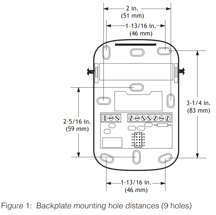
- Drill a hole in the wall at each of the marks.
- Insert a plastic anchor into each of the holes until they are flush with the wall.
- Thread the wires through the back of the backplate.
- Attach the backplate to the wall by screwing the supplied metal screws into the plastic anchors. Torque installation screws to 11 in-oz (79 Nmm).
- Connect each of the wires to the corresponding terminals on the backplate, as shown in Figure 2. Wire digital models as indicated on the label. Note that the meaning of the A and B symbols for EIA/RS-485 wiring varies among vendors.
Terminal 6 corresponds to BACnet “+”, the Modbus “D1”, and the EIA/RS-485 “B”. Terminal 5 corresponds to BACnet “-”, the Modbus “D0”, and EIA/RS-485 “A”. - Set the slide switches according to the configuration of the monitor.
- Align the bottom of the bezel with the mounting assembly and rotate the top into place. Press firmly until it snaps.
- Torque the case hex screws to 7-10 oz-in (0.59-0.85 Nm).

Duct mounting

The monitor can be mounted on a rectangular duct at least 7 in. × 7 in. (18 cm × 18 cm) or a round duct at least 24 inches (61 cm) in diameter by two sheet metal screws which are supplied in the installer’s kit. Do not mount the monitor on the top or bottom of a duct (the sampling tube is designed for horizontal installation).
Procedure:
- Make a 1 1/16-inch (27 mm) hole in the duct at the desired sampling location.
- Position the duct-mount bracket over the hole.
- With a pencil, mark the locations for the two mounting holes.
- Drill a hole in the duct at each of the marks.
- Attach the mounting plate to the duct with the supplied sheet metal screws. Torque the screws to 11 in-oz (79 Nmm).
- Slide the sampling tube through the mounting bracket up to the collar (shown in the following illustration).
- Torque the case hex screws to screws to 7-10 oz-in (0.590.85 Nm).
- Rotate the sampling tube until the divider shown in the crosssection illustration above is perpendicular to the flow of air in the duct.
- Lightly lubricate the connector O-ring with water to facilitate installation.
- Position the connector on the back of the monitor on the sampling tube connector and twist a quarter-turn counterclockwise. A tight fit is normal (the O-ring on the sampling tube provides a snug seal with the monitor). The monitor will snap into position when it is securely attached to the sampling tube. (The monitor can be rotated to any of four positions.)
- Tighten the mounting plate clamp screws.
- Conduit is attached to the bottom of the monitor in the same manner as standard electrical junction boxes.


First power-up
No calibration of the CO2 or VOC sensors is required at startup. The monitor will immediately begin operation with the default parameters mentioned in the Menus section. If desired, the monitor can be calibrated, however. Refer to the Technical Manual for calibration procedures.
Warm-up
Monitors equipped with CO2 sensors require a warm-up period at room temperature and 30-70% relative humidity. Typically, this is about 1 minute and is never more than 15 minutes. They will self-calibrate in 2 to 3 weeks. VOC sensors also require warm-up periods of up to 15 minutes after an initial base-lining with clean air. They will self-calibrate in 1 week.
Entering, saving, and changing passwords
The user’s password, a four-digit number, is entered by pressing the appropriate numbers on the touchscreen. As each number is selected, it is shown near the top of the display. After the four numbers are displayed, press [√ ]to proceed to the main menu.
Press [← ]to delete the last digit entered (repeat to delete more digits). Press [×] to return to the Default Display screen without entering a password.
The monitor will accept two passwords. A level-one password (0000 by default) will allow the user to, for example, modify the monitor’s temperature setpoints. A level-two password (2967 by default) would give the user access to additional functions such as constraining those setpoints to a certain range, customizing the default display, or changing passwords.
Part No. 1508-0102
Revision 3
July 2013