Honeywell Sensepoint XRL Fixed Gas Detector User Guide

Fixed Gas Detector
Quick Start Guide

Read and understand the Sensepoint XRL Instruction Manaul before installing, operating, or servicing this product. These are available for download from the Honeywell Analytics website. Visit www.honeywellanalytics.com.
Safety
Installation must be in accordance with the recognized standards of the appropriate authority in the country and locality concerned.
Analog (mA) Output Versions
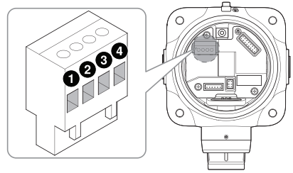

- +24 V DC or 24 V AC
- 4 to 20 mA
- 0 V or 24 V AC
- Common
Modbus RTU Output Versions

- +24 V DC or 24 V AC
- A
- 0 V or 24 V AC
- B
Securing the Detector to a Wall
- Determine where the detector is to be placed. Mark and drill holes as required.
- Secure the detector in its mounting position with suitable fixings appropriate to the mounting surface. Do not over-tighten.

Cable Connections
- Unscrew the front cover counterclockwise until it is open.
- Hold the handle of the main electronics module and pull it outward with a steady force. Do not pull sharply.
- Pull out the thread protector from the left cable entry, and remove the blanking plug from the right by turning it counterclockwise. If required, fit the blanking plug to the unused cable entry and tighten it.
- Fit suitable cable glands or conduits appropriate to the application and type of cable being utilized to the cable entries.
- Feed the cable through the cable gland.
- Pull the terminal blocks to remove them from the connector module.
- Connect cables to the terminal blocks, referring to the relevant wiring diagram. Strip and insert the end of each wire into the
corresponding terminal hole. Using a flat-blade terminal screwdriver, tighten the terminal screw until the wire is secured.
Use a ferrule on the wire where necessary. - Replace the terminal blocks in their correct positions.


Ground Connections
Effective grounding is crucial to ensure stable Modbus communications and to limit the effects of radiofrequency interference. A ground point is provided inside the housing. In order to prevent false readings or alarms as a result of ground loops, ensure that the shield of all cables is grounded at a single point, preferably at the controller. Consideration should also be given to how conduits and glands are also grounded.

NOTE
A connection for safety earth is provided at the top of the outside of the enclosure. This must be used to connect the enclosure to the electrical safety earth. Any earth regime must avoid earth loops.
Finalizing Installation
- Where used, tighten the sealing nut of the cable gland to secure the cable.
- Refit the main electronics module to the connector module.
- Replace the front cover by turning it clockwise ensuring that it is tight.
- Lock the front cover in position by tightening the grub screw.

Status Indicator
The detector features a status indicator on its front face.
Normal: The indicator flashes GREEN every 20 seconds when the concentration of the target gas is within normal range. The Normal indication can also be set to steady green or Off.
Alarm: RED flashes rapidly when the gas concentration is beyond the alarm-level threshold.
Fault: YELLOW flashes rapidly when the gas detector is in a fault state.
Bluetooth pairing: BLUE flashes when Bluetooth® pairing between the gas detector and a smartphone is in progress.
Bluetooth connected: Steady BLUE is lit when a Bluetooth connection is established.

Connecting to a Detector via Bluetooth
To pair your smartphone with a specific detector, follow these steps:
- Download Sensepoint App from Google Play Store. Install and launch the app.
- Create and register a user account, and log on with the created account information.
- To associate with the Sensepoint XRL gas detector, scan the QR code on the sheet included in the box or enter its Activation Key.
- Complete the installation of the detectors.
- On the app’s home screen, tap DETECTORS to scan for available detectors.
- Select a detector from the detector list to pair with it.
- Look for the detector whose Status Indicator is flashing blue.
- Tap Confirm Detector to pair with that detector. Otherwise, tap Return to list to select one of the others.
For more information, please refer to the Sensepoint App manual.
When a Bluetooth® connection is established, the detector’s reading is displayed on the app interface with the gas type and other information.
Specifications
| Physical specification | |
| Dimension | 118 mm × 159 mm × 93 mm (4.4 × 6.2 × 3.6 in) |
| Weight | 1400 g (3.1 lb) |
| Power supply | |
| DC input voltage (nominal) | † 24 V DC |
| AC input voltage (nominal) | ‡ 24 V AC, 50/60 Hz |
| Inrush current | Less than 850 mA |
| Maximum power consumption | |
| mA Versions | < 1.5 W (toxic), < 2.6 W (flammable) |
| Modbus versions | < 1.0 W (toxic), < 2.0 W (flammable) |
| Outputs§ | |
| Analog output | 0 to 22 mA sink or source (configurable) |
| Digital output | Modbus RTU |
| Operating Environment | |
| Operating temperature | −40 to 65 °C (−40 to 140 °F) |
| Storage temperature | 0 to 30 °C (32 to 86 °F) |
| Humidity | 0 to 99% (non-condensing) ¶ |
| Atmospheric pressure | 90 to 110 kPa |
| Ingress protection | IP66, NEMA 4X |
| Installation category | II (UL/CSA/IEC/EN 61010-1) |
| Pollution degree | 2 (UL/CSA/IEC/EN 61010-1) |
| Cable Gland | |
| ATEX/IECEx | M20 |
| cULus | ¾ NPT |
†mA versions: 11 to 32 VDC, Modbus versions: 9 to 32 VDC
‡20 to 27 VAC
§Dependent on version
¶Flammable catalytic versions: 10 to 90% RH. Operating the detector outside of this range may result in increased drift and a reduction in detector accuracy.
Certifications
- ATEX (DEMKO 17 ATEX 1872X)
Ex DB IIC T6 Gb
Ex tb IIIC T85°C Db
Tamb −40 to +65°C - IECEx (IECEx UL 17.0038X)
Ex DB IIC T6 Gb
Ex tb IIIC T85°C Db
Tamb −40 to 65°C - cULus
Class I, Division 1 & 2, Groups B, C, and D
Class II, Division 1 & 2, Groups E, F, and G
Class I, Zone 1, AEx de IIC T6
Zone 21, AEx tb IIIC T85°C, IP6X
Ex DB IIC T6 Gb
Ex tb IIIC T85°C DbX
Tamb −40 to +65°C, Temp Code T6


Keep this manual for later use. For full operating instructions:
3017M5034_1 HAA170035
© 2017 Honeywell Analytics
