Honeywell E3SAH E3point Gas Monitor User Guide


Honeywell E3SAH E3point Gas Monitor
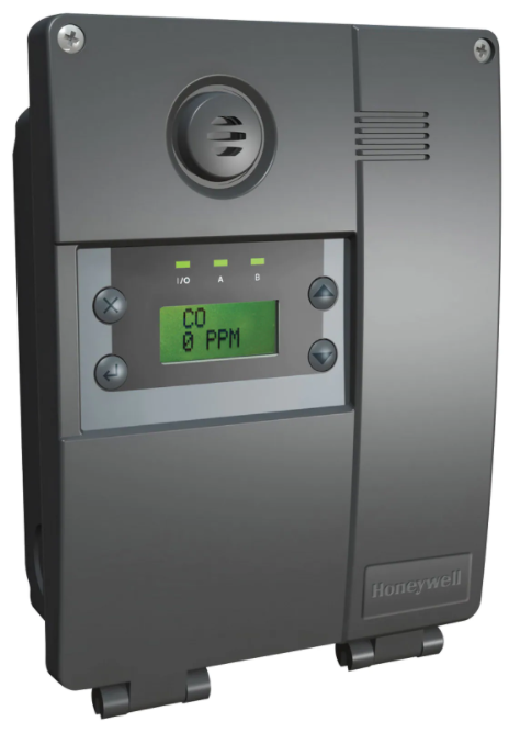

The E3Point® gas detection system combines a gas sensor (electrochemical or catalytic type), a control unit, a buzzer, a relay, and RS-485 in one reliable and robust product. The polycarbonate housing is resistant to rust, dents, and corrosion. It is well suited for commercial use in certain outdoor environments and indoor environments such as parking garages and mechanical rooms.
Installation
The main installation considerations are height and detection objectives. If the primary application is the fastest possible leak detection, mount the sensor near the potential leak sources. As a result, the indicated concentration may not be representative of personnel exposure, and easy access for the required calibration and maintenance can be compromised. If there are fans, wind, or other sources of air movement, gases may tend to rise or collect in certain areas of a facility. The local air currents should be assessed when selecting a sensor location. Air convection is often more important in determining gas concentration areas than vapor density factors. As a rule, at least one sensor should be located close to each point where an emission is likely to occur. The detector must be easily accessible for calibration and maintenance.
If personnel protection is the primary application, mount the unit in the “breathing zone” (3.5 to 5 ft., 1 to 1.5m) from the ground, within the range of a person’s respiration area. Protect the sensor from water, wash-down, and excessive humidity. To prevent electrical interference, keep sensor and wire runs away from mercury vapor lights, variable speed drives, and radio repeaters. Protect the sensor from physical damage (fork lifts, etc.). Do not mount the sensor over a door in a refrigerated area. For critical locations, more than one sensor should be installed in each room.
Never mount the sensor flat on a ceiling or on a vibrating surface.
| Detected Gas | Relative Density (air = 1) | Installation Height | |
| CO | Carbon monoxide | 0.968 | 1–1.5 m (3–5 ft.) from floor |
| H2S | Hydrogen sulfide | 1.19 | 30 cm (1 ft.) from floor |
| NO2* | Nitrogen dioxide | 1.58 (cold) | 30 cm–1 m (1–3 ft.) from ceiling |
| O2 | Oxygen | 1.43 | 1–1.5 m (3–5 ft.) from floor |
| Combustibles | Most combustibles are heavier than air, with the exception of methane, hydrogen, ethylene and acetylene. Sensors for gases that are heavier than air should be installed approximately 30 cm (1 ft) from the floor. For combustibles that are lighter than air, sensors should be installed 30 cm (1 ft) from the ceiling, close to the potential leak source. | ||
May differ in certain applications. Hot NO2 from exhaust systems is lighter than ambient air.
Duct Mounting
The E3Point® gas detector must be duct mounted using the custom housing provided with the duct mount version. All of the components housed within the housing are factory assembled. Gas detection in ducts works best for airflows between 500–4000 fpm.

- Measure and mark the holes for intake and exhaust tubes.
- Drill the holes in the duct for the sampling tubes (1 1/2 in. (38 mm) for the air intake tube, 1/2 in. (13 mm) for the air exhaust tube).
- Affix intake and exhaust tubes to the duct mount housing.
- Insert the tubes into the holes in the duct.
- Orient the air holes on the air intake tube to face the airflow.
- Attach the housing to the duct with four 8 x 3/4” galvanized or zinc-plated sheet metal screws (not provided).
- Remove one of the knockouts (depending on where cables will enter the housing) and affix appropriate conduit.
- Run wiring through the conduit and the housing to the monitor.
- Connect the wires (see the appropriate section below).
- Screw the cover onto the monitor and replace the housing cover.
Wall Mounting
Mounting is usually done on concrete walls or columns, but the unit can be mounted on any vertical surface or to a standard electrical junction box. The housing is designed with spacers on the back to allow moisture to flow behind the housing without affecting the unit. Mounting holes are located inside the housing.
- Open the unit and drill the holes, as shown in the illustration, (4 3/8” (11.1 cm) apart if mounting directly to a wall, or with the height 3.281” (8.3 cm) for electrical boxes. Do not remove the PC board when removing knockouts.
- Mount the unit securely using appropriate screws and anchors. The unit is designed to use #6 screws.
- Tighten to 8.7 in-lb (1 Nm) maximum.
- Close the unit cover and tighten the cover screws to 29.7 in-lb (3 Nm).

Wiring
Power wiring must comply with all applicable codes, but never should be less than #20 AWG; 120 VAC wiring should be #14 or #12 AWG. Signal wiring should be done with #20-24 AWG shielded twisted pair cable Belden 9841 or similar. Network units should have no more than 2,000 ft (600 m) of #22 AWG wire. Smaller gauge sizes are limited by the same resistance limit. Power wiring should never be less than #20 AWG. 120 VAC wiring should be #14 or #12 AWG. Power wiring is grounded at the screw and nut on the grounding plate inside the case.
Wiring Standalone Units
Ground the shield at the main control panel. Connect the shield wire in the sensor terminal block labeled “shield.” Tape all exposed shield wire at the sensor to insulate it from the enclosure.
Electrical Power: 24 VDC/VAC nominal, 0.35 amp maximum. Either AC or DC may be connected to the terminal block.
Output: Circuit board mounted sensor provides a linear 4-20 mA output. Monitoring equipment may have a maximum impedance of 500 ohms.
Circuit Board Connections: Connect the power wiring to terminal J1, communication wiring to terminal J2, and external devices (ventilators, strobes, etc. to relay terminals J5 or J6).
Relay Output: 2 DPDT relays, 5A @ 250VAC


The transformer is mounted under the PCB and connections to the power terminal are factory wired. Connect the live and neutral wires, as shown (ensure that power is off before attempting to connect the wires). Replace fuse with same type: 1A 250 VAC, T.
Connecting a Remote to the Main Unit
Signal wiring should be done with #20-24 AWG shielded twisted pair cable Belden 9841 or similar. Remote sensors should have no more than 200 ft (61 m) of #22 AWG wire. Smaller gauge sizes are limited by the same resistance limit.
The OUT1 and OUT2 connectors on the remote sensor’s terminal are not used. Do not connect wires to these locations.

Wiring Network Units

Ground the shield at the main control panel. Connect the shield wire in the sensor terminal block labelled “shield.” Tape all exposed shield wire at the sensor to insulate it from the enclosure.
Main circuit board connections:
- Connect power wiring to terminal J1
- Connect Communication wiring to terminal J2
- Connect external device (ventilator, strobe, etc) to relay terminal J5
User Interface
The E3Point® gas monitor is equipped with a 2-line, 8-character LCD screen that displays reading information and serves as an interface for programming functions and calibration.
Enter key: confirms selections and provides access to the programming menus
Escape key: cancels modifications and exits menus
LCD screen: displays the readings in real time, including the type of gas detected, the concentration, and measurement value (% or ppm) and for which sensor (built-in or remote)
Navigation controls: increment/decrement values and allow scrolling through menus

| LED Indicators | Description | Display Modes |
| I/O | Power | Always on = Normal operation |
| Always off = microcontroller fault or no power | ||
| Blinking (twice per second) = self test | ||
| 1 | Standalone: Built-in Sensor | Always on = Alarm A triggered |
| Slow blink (once per second) = Alarm B/C triggered | ||
| Network: Built-in Sensor Alarm A |
Fast blink (4 times per second) = Fault | |
| Always off = normal operation | ||
| 2 | Standalone: Remote Sensor |
Always on = Alarm A triggered |
| Slow blink (once per second) = Alarm B/C triggered | ||
| Fast blink (4 times per second) = Fault | ||
| Always off = normal operation | ||
| Network: Transmit |
Always on when transmitting, blinks for communication | |
| Always off = normal operation |
Detection Ranges and Alarm Levels
| Gas Detected |
Range |
Alarm A |
Alarm B |
Alarm C |
Maximum Overload* | |
| CO | Carbon monoxide | 0-250 ppm | 25 ppm | 100 ppm | 225 ppm | 500 ppm |
| H2S | Hydrogen sulfide | 0-50 ppm | 10 ppm | 15 ppm | 20 ppm | 150 ppm |
| NO2 | Nitrogen dioxide | 0-10 ppm | 0.7 ppm | 2 ppm | 9 ppm | 1000 ppm |
| O2 | Oxygen | 0-25%vol | 19.5%vol. | 22%vol. | 22.5%vol | 100%vol |
| COMB | Combustibles | 0-100%LEL | 25%LEL | 50%LEL | 90%LEL | 100 %LEL |
| *Sensor exposure to gas concentration that may result in permanent damage to the sensor. | ||||||
Limited Warranty
Honeywell Analytics, Inc. warrants to the original purchaser and/or ultimate customer (“Purchaser”) of Honeywell products (“Product”) that if any part thereof proves to be defective in material or workmanship within one (1) year, such defective part will be repaired or replaced, free of charge, at Honeywell Analytics’ discretion if shipped prepaid to Honeywell Analytics at 4005 Matte Blvd., Suite G, Brossard, Quebec, Canada, J4Y 2P4, in a package equal to or in the original container. The Product will be returned freight prepaid and repaired or replaced if it is determined by Honeywell Analytics that the part failed due to defective materials or workman-ship. The repair or replacement of any such defective part shall be Honeywell Analytics’ sole and exclusive responsibility and liability under this limited warranty.
Re-Stocking Policy
The following re-stocking fees will apply when customers return products for credit: A 15% re-stocking fee will be applied if the product is returned within 1 month following the shipping date. A 30% re-stocking fee will be applied if the product is returned within 3 months following the shipping date. A full credit (less re-stocking fee) will only be issued if the product is in perfect working condition. If repairs are required on the returned product, the cost of these repairs will be deducted from the credit to be issued. No credits will be issued beyond the three month period.
Exclusions
If gas sensors are part of the Product, the gas sensor is covered by a twelve (12) month limited warranty of the manufacturer.
If gas sensors are covered by this limited warranty, the gas sensor is subject to inspection by Honeywell Analytics for extended exposure to excessive gas concentra-tions if a claim by the Purchaser is made under this limited warranty. Should such inspection indicate that the gas sensor has been expended rather than failed prematurely, this limited warranty shall not apply to the Product. This limited warranty does not cover consumable items, such as batteries, or items subject to wear or periodic replacement, including lamps, fuses, valves, vanes, sensor elements, cartridges, or filter elements.
Warranty Limitation and Exclusion
Honeywell Analytics will have no further obligation under this limited warranty. All warranty obligations of Honeywell Analytics are void if the Product has been subject to abuse, misuse, negligence, or accident or if the Purchaser fails to perform any of the duties set forth in this limited warranty or if the Product has not been operated in accordance with instructions, or if the Product serial number has been removed or altered.
Disclaimer of Unstated Warranties
The warranty printed above is the only warranty applicable to this purchase. All other warranties, express or implied, including, but not limited to, the implied warran-ties of merchantability or fitness for a particular purpose are hereby disclaimed.
Limitation of Liability
It is understood and agreed that Honeywell Analytics’ liability, whether in contract, in tort, under any warranty, in negligence or otherwise shall not exceed the amount of the purchase price paid by the purchaser for the product and under no circumstances shall Honeywell Analytics be liable for special, indirect, or consequential damages. The price stated for the product is a consideration limiting Honeywell Analytics’ liability. No action, regardless of form, arising out of the transactions under this warranty may be brought by the purchaser more than one year after the cause of actions has occurred.
