Honeywell DX100i Termination Unit User Guide

Quick Start Guide


INTRODUCTION
The DX100 (I) Termination Unit is an explosion-proof junction box that provides a signal connection point and mounting point for the Honeywell Analytics Searchpoint Optima or Optima Plus gas detectors.
Caution: The DX100 (I) Termination Unit can only be used with
Searchpoint Optima or Optima Plus gas detectors.
This guide covers the basic on-site mechanical and electrical installation of the unit. Refer to the DX100 Series Termination Units Technical Handbook (Part No: 2104M0701) for more detailed information about the DX100 (I).
The unit is certified to UL and CSA standards and is intended for use in hazardous environments. The DX100 (I) provides:
- terminals for connecting the gas detector and the field cabling
- an Intrinsically Safe (IS) connection point for the Hand Held Interrogator (SHC1)
- a local mounting point for the Searchpoint Optima or Optima Plus gas detector
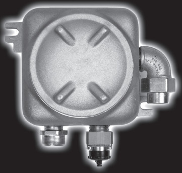
The unit features:
- three 3/4″ NPT cable/conduit entries
- two terminal blocks
- a voltage clamp and a communications link entry socket
One of the three cable/conduit entries (usually the left-hand one) is used to mount the Searchpoint Optima or Optima Plus gas detector directly to the box. The Optima and Optima Plus output a 4-20mA signal that is sent via the Termination Unit field-wiring back to the controller.
The voltage clamp and the external socket provide the IS connection to the Handheld Interrogator (SHC1).
The SHC1 allows the operator to communicate with the attached gas detector to the commission, calibrate or diagnose the system.
Full details about the Searchpoint Optima and Optima Plus units can be found in their documentation, which includes the operation of the SHC1.
Caution: Only the SHC1 Handheld Interrogator must be connected to the
DX100 (I) Communications Link Entry Socket.
Honeywell Analytics Limited reserve the right to change or revise the information supplied in this document without notice and without obligation to notify any person or organization of such revision or change. If further details are required that do not appear in this document contact Honeywell Analytics Limited or one of its agents.
SAFETY
Ensure that you read and understand this document BEFORE installing/ operating the equipment. Pay particular attention to the Safety Warnings.
WARNINGS
- The DX100 (I) Termination Unit is certified for and intended for use in potentially hazardous areas. Install and use the DX100 (I) Termination Unit in accordance with the latest regulations. No modifications to the unit is permitted without reference to the relevant certifying authority
- Install UL-approved and certified equipment including field wiring in strict accordance with the articles of the National Electrical Code for Division 1 Hazardous Locations (NFPA 70).
- Install CSA-approved and certified equipment including field wiring in strict accordance with Canadian Electrical Code, Part 1.
- For installations elsewhere, the appropriate local or national regulations should be used.
- The Code of Practice regarding Selection, Installation, Use, And Maintenance Of Apparatus For The Detection Of Combustible Gases (Other Than For Mining Applications Or Explosive Processing And Manufacture) must be complied with.
- The DX100 (I) Termination Unit must be properly earthed to protect against electrical shock, minimize electrical interference and comply with IS Safety Requirements.
- Dismantling or repair of equipment should be carried out in the safe area only.
- Do not drill holes in the housing as this will invalidate the explosion protection.
- In order to maintain electrical safety, the unit must not be operated in atmospheres with more than 21% oxygen.
- Do not open the enclosure in the presence of an explosive atmosphere.
CAUTIONS
- Only the Handheld Interrogator (SHC1) must be connected to the Termination Unit’s communication link entry socket.
- The DX100 (I) Termination Unit can only be used with Searchpoint Optima or Optima Plus gas detectors.
MAIN FEATURES
This section identifies the main features of the Termination Unit and also details important dimensions for the unit when installing.

INSTALLATION
It is important before starting these procedures that the detailed information provided in the DX100 Series Termination Units Technical Handbook about DX100 (I) installation has been carefully considered at the planning stage.
The following points should be noted.
General Installation Guidelines
- Read the Warnings and Cautions at the beginning of this document and all the relevant instructions before starting any of the installation procedures.
- Identify external cable requirements and the necessary cable entry ports to be used on the Termination Unit.
- Refer to the documentation for the associated control system for details about external network connection information, field wiring, interconnections, etc.
- Refer to the associated Searchpoint Optima handbook for details about the gas detector.
MECHANICAL INSTALLATION
Mechanical Installation Guidelines
- Identify a suitable location where the Termination Unit can be mounted. The unit should be fitted to a flat surface.
- When fitting a Termination Unit consideration should be made regarding the probability of mechanical impacts and interference from other equipment and
Procedure
This procedure describes how the DX100 (I) is installed at the mounting location and then the Optima gas detector is fitted to the Termination Unit.
- Securely fit the Termination Unit at the required monitoring point.
Use the two Termination Unit mounting lugs. Ensure the communications link entry socket connector is located at the bottom. This is to fulfill the requirement to position the Optima sensor horizontally so that the risk of fouling the gas detector’s optical surfaces is reduced. - Remove the Termination Unit lid.
Use the lugs on the lid to unscrew it anticlockwise from the Termination Unit base. - Fit the Optima or Optima Plus detector to the left-hand entry. First, remove the 3/4 NPT approved blanking plug.
- Fit approved certified 3/4 NPT cable glands or conduit fittings to the Termination Unit cable/conduit entries as required.
- Fit the external field wiring through the cable/conduit fittings and secure.
- Terminate the Optima and field wiring.
Refer to Electrical Installation.
The diagram shows a typical Searchpoint Optima Plus and DX100 (I) installation.

ELECTRICAL INSTALLATION
Electrical Installation Guidelines
- Isolate all associated power supplies and ensure that they remain OFF during the
- Ensure that approved and certified cable glands have been fitted to the Termination Unit cable entries were used for field wiring, with sealing washers were necessary to maintain the ingress protection rating.
- Ensure that any cable gland/conduit locking rings are fitted before terminating the
- Make sure that a conduit sealing fitting is installed within 460mm (18in.) of the Termination Unit on all conduit runs.
- Ensure that approved and certified blanking plugs are fitted to all unused Termination Unit cable
- The Termination Unit mounting plate must be bonded to protective earth.
- Suitable crimps and/or ferrules must be fitted when connecting more than one wire to a Termination Unit terminal.
- The field terminals of the Termination Unit accept single or multi-stranded wire from 22-12 AWG (0.326 to 3.31mm2). Cables should be routed carefully to avoid physical and environmental hazards such as mechanical stress and high temperatures.
- In order to ensure correct operation and to meet requirements for RFI and EMC, it is recommended that all field cables are screened with the cable screen connected at one end only (see the DX100 Series Technical Handbook for further details – Part No: 2104M0701).

Procedure
Connect the gas detector and field wiring to the terminal blocks in the DX100 (I) Termination Unit according to the following wiring diagram and table.

| Terminal/ Number | Gas Detector Wiring | Field Wiring | ||
| Function | Colour | |||
| TB1 | 1 | – | – | – |
| 2 | A | Orange | – | |
| 3 | B | Blue | – | |
| 4 | – | – | – | |
| TB2 | 1 | +24VDC | Red | – |
| 2 | – | – | +24VDC – Supply | |
| 3 | 4-20mA | White | 4-20mA – Output | |
| 4 | – | – | – | |
| 5 | OV | Black | – | |
| 6 | – | – | OV – Supply | |
| Earth Posts | – | Earth | Green/Yellow | Earth Barrier Earth |
SPECIFICATIONS
| Inputs | Searchpoint Optima Searchpoint Optima Plus Field wiring. |
| Outputs | IS protected SHC1 Handheld Interrogator communications (RS485) 4-20mA (Non-isolated). |
| Power Supply | 18-32VDC. |
| Environmental | |
| Operating temperature | UL -25°C to 40°C (-40°F to 104°F). CSA -55°C to 40°C (-67°F to 104°F). |
| Enclosure | |
| Entry Socket | One IS protected Communications Link Entry Socket for connecting the SHC1 Handheld interrogator. |
| Cable/Conduit Entries | Three 3/4 NPT entries (one on each side and one in the bottom) to accept gas detector and field cabling or 3/4″ conduit. |
| Size | 212mm (8.35in.) wide x 152.4mm (6in.) high x 117.5mm (4.625in.) deep. Add approximately 60mm (2.36in.) to the height for the Communications Link Entry Socket. |
| Weight | 2.5kg. Aluminum. |
| Material Ingress | IP66 to BS EN 60529:1992, Degrees of protection provided by enclosures (IP code). |
| Protection Certification | UL Class 1, Div 1, Groups B, C, D CSA Class 1, Div 1, Groups B, C, D (see 6. Certification for details) |
| Field Wiring | 22-12 AWG (0.326 to 3.31mm2), 105C |
CERTIFICATION
This section specifies UL and CSA certification information for the DX100 (I) Termination Unit. It includes relevant Control Drawings.
A Honeywell Analytics certification label is located on the right-hand side of the DX100 (I) Termination Unit.
The label contains all the relevant information regarding the product’s identification and certification state.
The part number of the certified UL/CSA DX100 (I) Termination Unit is 2104B2381.
The following diagrams show the Honeywell Analytics UL and CSA Certification Labels. The label content for the CSA label is explained. The UL label is similar.

UL Control Drawing

- APPARATUS WHICH IS UNSPECIFIED EXCEPT THAT IT MUST NOT BE SUPPLIED FROM, NOR CONTAIN IN NORMAL OR ABNORMAL CONDITIONS A SOURCE OF POTENTIAL WITH RESPECT TO EARTH IN EXCESS OF 250V runs OR 250V d.c.
- WIRING FROM THE HANDHELD CALIBRATOR (SHC1) TO THE TERMINATION UNIT (DX100) IS NOT TO EXCEED 15 METRES MAX.
- INSTALL EQUIPMENT INCLUDING FIELD WIRING IN ACCORDANCE WITH ARTICLES OF THE NATIONAL ELECTRICAL CODE FOR DIVISION 1 HAZARDOUS LOCATIONS.
CSA Control Drawing

NOTES:
- APPARATUS WHICH IS UNSPECIFIED EXCEPT THAT IT MUST NOT BE SUPPLIED FROM, NOR CONTAIN IN NORMAL OR ABNORMAL CONDITIONS A SOURCE OF POTENTIAL WITH RESPECT TO EARTH IN EXCESS OF 250V RMS OR 250V cl. c.
- WIRING FROM THE HANDHELD CALIBRATOR (SHC1) TO THE TERMINATION UNIT (DX100) IS NOT TO EXCEED 15 METRES MAX.
- INSTALL EQUIPMENT INCLUDING FIELD WIRING IN ACCORDANCE WITH CANADIAN ELECTRICAL CODE. PART 1.
