Honeywell IntelliDoX Docking Module for BWC4 User Guide


Honeywell IntelliDoX Docking Module for BWC4

Intended Use
Unless otherwise specified at time of purchase, IntelliDoX modules shipped from Honeywell.
- Are factory configured for use with portable gas detectors.
- Operate as stand-alone bump test and calibration stations.
- May be connected to a network via Ethernet cable for enhanced access to and control of administrative and maintenance tasks.
- Are compatible with PC Configuration software.
- If the IntelliDoX module or any of its parts are damaged or missing, contact Honeywell or an authorized distributor immediately.
Normal Operating Conditions
The IntelliDoX is designed to be safe under the following conditions:
- Indoor use only
- Normal atmosphere (20.9% O2) that is free of hazardous gas
- Temperature range of +10°C to +35°C
- Relative humidity of 0% to 50%
If the intended operating environment does not match these criteria, Honeywell recommends that you consult a qualified professional specialist prior to installing and using any IntelliDoX modules. This equipment uses potentially harmful gas for calibrations. The IntelliDoX must be attached to a venting system or be used in a well-ventilated area.
About this Publication
This publication is a quick-start reference guide to assembling the IntelliDoX Docking Module, and preparing it for first use. Ensure that you are familiar with the use of personal gas detection devices and accessories, and take appropriate action in the event of an alarm condition. For additional information regarding IntelliDoX installation, configuration, operation and maintenance, refer to the IntelliDoX User Manual at https://www.honeywellanalytics.com/en/products/ IntelliDox
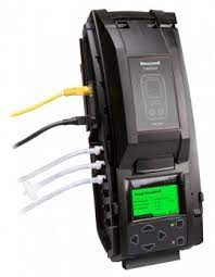
About the IntelliDoX Docking Module
The IntelliDoX Docking Module (‘IntelliDoX’ or ‘IntelliDoX module’) is an automatic bump test and calibration docking station for use with portable gas detectors manufactured by Honeywell. The IntelliDoX automatically performs essential procedures including sensor identification, bump tests, calibrations, alarm tests and data transfers. It also retains a cumulative record of detector data logs that are transferred to its onboard memory. The IntelliDoX can be used on a tabletop or other flat surface. A built-in retractable stand can be deployed to hold the IntelliDoX upright at an angle that is suitable for routine use. IntelliDoX modules can also be mounted on a wall or other flat surface. For additional information, refer to the User Manual.
What’s in the Box
IntelliDoX Docking Module Each IntelliDoX. Docking Module package contains one IntelliDoX module with a factory-installed nest. The power adapter, power cord, calibration gas tubing and exhaust tubing, are packaged separately as the IntelliDoX Enabler Kit. One Enabler Kit is required for each stand-alone IntelliDoX module. If the IntelliDoX module is damaged or if parts are missing, contact Honeywell or an authorized distributor immediately.
IntelliDoX Enabler Kit
One IntelliDoX Enabler Kit is required for each stand-alone
IntelliDoX module. Each Enabler Kit contains:
- Power supply and AC power cord appropriate to shipping destination.
- Ethernet cable.
- Calibration gas and purge gas tubing, cut to 1 meter (3.3 feet).
- Quick connect fittings.
- Exhaust tubing, cut to 4.57 meters (15 feet).
- Inlet (purge) filter assembly.
- IntelliDoX end plate.
- Download PC Configuration software that supports your product from the Honeywell Analytics website. https:// www.honeywellanalytics.com/en/products/IntelliDox If Enabler Kit parts are damaged or missing, or if additional Enabler Kits are required, contact Honeywell or an authorized distributor immediately.
Copyright, Notices, Trademarks
While this information is presented in good faith and believed to be accurate, Honeywell disclaims the implied warranties of merchantability and fitness for a particular purpose and makes no express warranties except as may be stated in its written
agreement with and for its customers. In no event is Honeywell liable to anyone for any indirect, special or consequential damages. The information and specifications in this document are subject to change without notice.
IntelliDoX is a trademark of Honeywell. Other brand or product names are trademarks of their respective owners.
Configuration Software
Please download PC configuration software on the IntelliDoX product page under the software tab on the Honeywell Analytics website. www.honeywellanalytics.com
| Product | Configuration Software |
| IntelliDoX BWClip |
Fleet Manager/SafetySuite DC |
| IntelliDoX BW MicroClip | Fleet Manager/SafetySuite DC |
| IntelliDoX BW Clip4 | Fleet Manager/SafetySuite DC |
| IntelliDoX BW Ultra | Fleet Manager/SafetySuite DC |
| IntelliDoX BW Solo | SafetySuite DC |
Symbol Definitions
This manual uses the following signal words, as defined by ANSI Z535.4-1998.
| Signal Word | Description |
| DANGER |
Hazardous situation which, if not avoided, will result in death or serious injury. This symbol identifies the most extreme hazardous situations. |
| WARNING | Hazardous situation which, if not avoided, could result in death or serious injury. |
| CAUTION | Hazardous situation which, if not avoided, may result in moderate or minor injury. |
| NOTICE | Situations which, if not avoided, may result in property damage. |
Important Safety Information: Read First
- To ensure personal safety, read Safety Information and Warnings before using the IntelliDoX.
- Use the IntelliDoX only as specified by the manufacturer. Failure to do so may impair protection provided by the IntelliDoX.
- The safety and security of any system or network incorporating the IntelliDoX and its accessory components is the responsibility of the assembler of the system.
- Follow all required National Electric Codes (NEC) and safety standards.
Prepare for First Use
To ensure that the IntelliDoX module is ready for safe operation, you must attach the endplate, attach the purge inlet filter assembly, and connect the exhaust tubing before you connect power or attach a gas cylinder.
Attach the Endplate
Each IntelliDoX Enabler Kit contains one endplate. To prevent gas leaks, the end plate must be attached and locked with the lock latch arm before connecting power supply or connecting gas cylinders. The end plate must remain securely latched at all times during operation. If the end plate is detached during operation, disconnect power and replace the end plate immediately.
- Unhook and lift latch arm.
- Attach end plate.
- Lower and lock latch arm.
This symbol indicates that the product must not be disposed of as general industrial or domestic waste. This product should be disposed of through suitable WEEE disposal facilities. For more information about disposal of this product, contact your local authority, distributor or the manufacturer.
At a Glance

| P a r t | N um |
| Lid | 1 |
| Lid button | 2 |
| View screen | 3 |
| Navigation buttons | 4 |
| Gas module | 5 |
| Arm | 6 |
| Arm unlock | 7 |
| Hinge | 8 |
| Panel latch | 9 |
| Detachable back panel | 10 |
| Expansion module | 11 |
| Network connection | 12 |
| Power connection | 13 |
| Exhaust outlet | 14 |
| Purge inlet | 15 |
| Gas inlet 1 | 16 |
| Gas inlet 2 | 17 |
| Gas inlet 3 | 18 |
| Gas inlet 4 | 19 |
| End plate | 20 |
Touchpad and buttons
| B u t t o n | A c t i o n |
| Move right | |
| Move left | |
| Move up | |
| Move down | |
|
|
Select menu item Save changes |
|
|
Close menu item Return to previous screen Cancel changes |
LCD Backlight
| Backlight Color | Status |
| Gray | Idle |
| Blue | Prompt for user action |
| Yellow | Activity in progress |
| Green | Activity successful |
| Red |
Warning Activity Failed |
Connect the Purge Inlet Filter Assembly
Each IntelliDoX Enabler Kit contains one purge inlet filter assembly. Unless otherwise specified, the purge inlet is configured to use ambient air in a fresh air environment with a normal atmosphere of 20.9% O2 that is free of hazardous gas. Ensure that the purge inlet filter assembly is attached before using the IntelliDoX module. You may attach an extension tubing to the filter assembly to draw ambient air from an adjacent fresh air environment.
- Ensure that the filter assembly is free of obstructions and defects.
- Connect the filter assembly to the purge inlet.
- If necessary, attach an extension tubing to the filter assembly to draw ambient air from an adjacent fresh air environment.
Connect the Exhaust Tubing
Each IntelliDoX Enabler Kit includes one exhaust tubing that is 4.57 meters (15 feet) long.
- Inspect the exhaust tubing to ensure that it is free of obstructions and defects.
- Connect the exhaust tubing to the exhaust outlet.
- Ensure that the exhaust tubing is not connected to a negative pressure system, or obstructed in any way.
Connect the Power
Each IntelliDoX Enabler Kit contains one power supply and AC power cord. Use only the power supply provided in the Enabler Kit to connect the IntelliDoX Docking Module to an appropriate electrical power outlet. When the power is connected, the IntelliDoX activates and a self-test is performed.
- Connect the AC power cord to the power supply
- Connect the power supply to the IntelliDoX power port.
- Plug the AC power cord into a suitable wall outlet.
- When the power is connected, the IntelliDoX LCD activates and a self-test is performed.
NOTICE
To prevent the corruption or loss of data and/or software and/or firmware, do not deactivate the equipment while performing datalog transfers, bump tests, calibrations or other operations.
Charge a Detector
Use the IntelliDoX to charge detectors fitted with rechargeable batteries. For more information on battery maintenance, refer to the detector manual.
- Charge only in a normal environment that is 20.9% O2 and free of hazardous gas. Do not operate the docking module in a hazardous area. Failure to adhere to this guideline can result in possible personal injury and/or property damage.
- Deactivate the detector.
- Insert the detector into the IntelliDoX module.
- Battery charging begins immediately. Battery charging is disabled during bump test and calibration procedures. Once tests and other routines are completed, you may leave the detector in the module for charging. If the detector is activated, the module will deactivate it after 10 minutes of inactivity. When charging is complete, remove the detector. Do not store the detector in the module.
Prepare for Bump Tests and Calibrations
The IntelliDoX module is factory-configured for use with portable gas detectors. Gas inlets are configured at the factory. Inlet configurations cannot be altered. The IntelliDoX Enabler Kit includes quick connect fittings and calibration tubing cut to the minimum recommended length of 1 meter (39 inches). Use only tubing that is between 1 meter (39 inches) and 10 meters (33 feet) in length when you connect gas cylinders to an IntelliDoX module.
Connect Calibration Gas
- Connect a demand flow regulator to the calibration gas cylinder.
- Use the quick connect fittings and calibration gas tubing to connect the calibration gas cylinder to the gas.
Bump Test

Bump test is a procedure that confirms a detector’s ability to respond to target gases by exposing the detector to gas concentrations that exceed its alarm setpoints.
If AutoBump on Insertion is set using PC configuration software, then bump test starts automatically when IntelliDoX recognizes the detector. If AutoCal on Overdue Sensors is enabled and if a calibration is also due, then no bump test is performed. Instead, calibration starts automatically when the detector is recognized.
- Insert a detector.
- Press and on the keypad to move to Bump test my detector on the IntelliDoX user menu.
- Press to select Bump Test. The LCD screen background changes to yellow and the bump test progress screen is displayed.
- The bump test begins. Test sequence progress screens are displayed while the tests are performed.
- If AutoDownload Datalog is set using PC configuration software, detector datalogs are automatically transferred to IntelliDoX.
Bump Test Pass

When the bump test is successful, LCD screen background changes to green and Bump test passed message is displayed. Alarm response and sensor response test items are checked. Press to return to IntelliDoX user menu.
Bump Test Fail

When the bump test fails, LCD screen background changes to red and Bump test failed message is displayed. Failed alarm response and/or sensor response test items are marked with . If the AutoCal on Failed Bump is set using PC configuration software, calibration automatically begins.
Calibration
Calibration is a two-step procedure that determines the measurement scale for the detector’s response to gas. In the first step, a baseline reading is taken in a clean, uncontaminated environment. In the second step, the sensors are exposed to known concentrations of gas. The detector uses the baseline and known gas concentrations to determine the measurement scale.
Calibration Guidelines
- Calibrate only in a normal environment that is 20.9% O2 and free of hazardous gas. Do not operate the docking module in a hazardous area. Failure to adhere to this guideline can result in possible personal injury and/or property damage.
- Use only premium grade calibration gases and cylinders that are approved by Honeywell, and supplied by Honeywell or an authorized distributor. The calibration gases must meet the accuracy of the detector. For more information, refer to the User Manual.
- Do not use a gas cylinder beyond its expiration date
- All calibration cylinders must be used with a demand flow regulator and must meet these maximum inlet pressure specifications. Disposable cylinders: 000 psig/70 bar, refillable cylinders: 03000 psig/207 bar
- Do not calibrate the detector during charging or immediately after charging.
- Calibrate the sensor if ambient gas readings vary during startup.
- Calibrate a new sensor before use. Allow the sensor to stabilize before starting calibration.
- Used sensor: wait 60 seconds
- New sensor: wait 5 minutes
- When calibrating the same gas detector multiple times, wait 10 minutes between calibrations to allow the sensor to stabilize.
- If a certified calibration is required, contact Honeywell or an authorized distributor.
Calibrate a Detector

AutoCal on Overdue Sensors is set using PC configuration software and sensors are overdue, then calibration starts automatically once IntelliDoX recognizes the detector.
- Insert a detector.
- Use and to move to Calibrate my detector on the IntelliDoX user menu.
- Press to select Calibrate my detector. The LCD screen background changes to yellow and the calibration progress screen is displayed.
- Calibration begins. Progress screens are displayed while the tests are performed.
- If AutoDownload Datalog is set using PC configuration soft ware, detector datalogs are automatically transferred to IntelliDoX.
Calibration Pass

When the calibration is successful, LCD screen background changes to green and Calibration passed is displayed. Alarm response and sensor response test items are checked. Press to return to IntelliDoX user menu.
Calibration Fail
When the calibration fails, LCD screen background changes to red and Calibration failed is displayed. Failed alarm response and/or sensor response test items are marked with.
