Dell EMC PowerStore User Guide

PowerStore
Quick Start

Before you begin
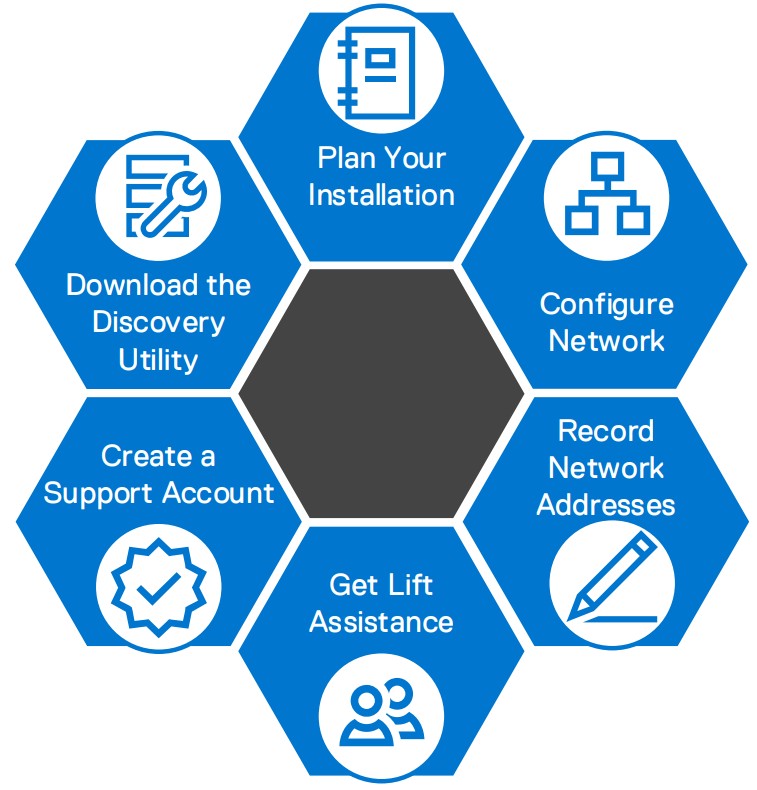
- Download the PowerStore Discovery Utility at http://dell.com/powerstoredocs.
This tool helps you discover your appliances within your network if you are remote. - Create a support account at https://dell.com/support. You need this account later in the configuration process to activate the software license and configure Dell EMC SupportAssist.
- Configure the network: Depending on the model of your system, read the PowerStore Networking Guide for PowerStore X Models or the PowerStore Networking Guide for PowerStore T Models at http://dell.com/powerstoredocs.
- Record network addresses: Download the Initial Configuration Worksheet from http://dell.com/powerstoredocs, and work with your network administrator to obtain the required network-related information.
- Get lift assistance: Obtain the help of a second person to install the enclosure into the rack or use a mechanical lift.

Note: If your appliance arrived pre-racked, begin installation at Step 5 of this guide.
Installation workflow
All rights reserved. Dell, EMC, Dell EMC, and other trademarks are
trademarks of Dell Inc. or its subsidiaries.
Other trademarks may be trademarks of their respective owners.
P/N 300-015-629 Rev 02


Verify that you have the following:
Base enclosure:
- 2U base enclosure (1)
- Rails (2)
- Power cables (6, only 2 required per enclosure)
- Mini-SAS HD cables (2)
- Bezel, with key (1)
- Electrostatic discharge clip (1)
- Network cables (4)
- Rack label and tags for emergency shutdowns
Expansion enclosure (optional):
- 25-drive expansion enclosure (1)
- Rails (2)
- Mini-SAS HD cables (2)
- Power cables (4, only 2 required per enclosure)
- Bezel, with key (1)
- Electrostatic discharge clip (1)
- Cable label sheet (3)
Decide where to install the base enclosure
- Install your base enclosure in the lowest possible space, leaving 2U of space open at the bottom of your cabinet for serviceability.-
- If installing an expansion enclosure, install the expansion enclosure in the next available 2U space, directly above the base enclosure or the last expansion enclosure in the system.
- Leave 4U at the top of the rack for network switches.

When installing the rails, ensure that the rail pins are lined up correctly:
• For the front end of the rail, the bottom pin of the rail goes through the middle hole of the lower U, and the top pin goes through the top hole of the upper U.
• For the rear end of the rail, the bottom pin of the rail goes through the bottom hole of the lower U, and the top pin goes through the top hole of the upper U.
- Position the rail so the label FRONT is located at the front of the rack and facing towards the inside of the rack while orienting the rear of the rail to align level with the holes on the rear of the rack.
- From the rear of the rack, pull the rail straight back until the latch is locked.
- To install the front of the rail, press the blue latch release button until the latch rotates open.
- Pull the rail forward until the pins slide into the holes on the front of the rack, then release the latch to secure the rail in place.
- Repeat for the other rail.
Note: Racks are shown with round holes. The installation instructions are the same for racks with square holes. For racks with threaded holes, remove the guide pin on the rails before installation.


The enclosure is heavy and should be installed into or removed from a rack by two people. To avoid personal injury and/or damage to the equipment, do not attempt to lift and install the enclosure into a rack without a mechanical lift and/or help from another person.

- From the front of the rack, slide the base enclosure onto the rails.
Ensure that the enclosure is flush with the front of the rack, fully seated in the cabinet, and does not easily slide out. - (Optional) If securing the system for shipment in the cabinet or for other unstable environments:
Locate the captive screw under each latch and tighten it to the front of the cabinet using a #1 Phillips screwdriver.


Locate and record the number from the black Dell Service Tag on the front of the base enclosure.


For each additional expansion enclosure, repeat steps 2 and 3 to install the rails and expansion enclosure onto the rails.
If you are not installing an expansion enclosure, continue to step 7.

Before you begin:
Select a single color of cable labels for use on all the enclosures in the appliance. Apply cable labels at each end of the following cables:
- Node to first expansion enclosure
- Node to last expansion enclosure
- Expansion enclosure to expansion enclosure
Cable both embedded modules on the base enclosure to the link control card (LCC) on the new expansion enclosure:
- Connect node A, SAS port B to LCC A, port A on the expansion enclosure (1).
- Connect node B, SAS port B to LCC B, port A on the expansion enclosure (2).
- Connect node B, SAS port A to LCC A, port B on the expansion enclosure (3).
- Connect node A, SAS port A to LCC B, port B on the expansion enclosure (4).


- For PowerStore T model deployments, cable the management interface on both nodes to a management switch or network.
Note: You may require two additional network cables to complete this step.Note: For FC-only block-optimized PowerStore T model configurations: You can choose to skip the following steps if you do not plan on configuring or using the replication, import, file, or iSCSI features. During the initial configuration process, in the Storage Network step, select the Configure Later option to generate placeholder IPv6 addresses.
- Connect your base enclosure to two switches to ensure a strong layer of redundancy.
Cable the Ethernet switches together by connecting two 100GbE ports of the bottom switch to two 100 GbE ports of the top switch.
- Connect the network cables on node A:
a. Port 0 of the embedded module connects to switch 1.
b. Port 1 of the embedded module connects to switch 2. - Connect the network cables on node B:
a. Port 0 of the embedded module connects to switch 2.
b. Port 1 of the embedded module connects to switch 1.


These instructions show a minimum cabling configuration. For more detailed instructions on recommended networking configurations and best practices, see the PowerStore Networking Guide for PowerStore T Models or PowerStore Networking Guide for PowerStore X Models at http://dell.com/powerstoredocs. Check with your network administrator to determine which ports on your switches to use.

a. Expansion enclosure
Connect the power cable to the power supply and close the retention bail over the base of the power cable. Connect the other end of each power cable to PDU A and PDU B. Repeat for all enclosures racked.
Plug each power cable into the base enclosure power supply unit and close the retention bail over the base of the power cable. Connect the other end of each power cable to PDU A and PDU B. After you connect the power cables, the base enclosure automatically starts up.


Attach the bezel
- Align the bezel with the expansion enclosure.
- Gently push the bezel into place on the cabinet until it latches.
- Lock the bezel with the provided key.
a. Base enclosure |
b. Expansion enclosure |


Next, discover your newly installed base enclosure, and then create a cluster.
Note: The procedure in this section only applies if you are physically present within the data center. If you do not have access to the base enclosure, refer to the PowerStore Networking Guide for PowerStore X Models or the PowerStore Networking Guide for PowerStore T Models for more information on remote discovery options.
Before you begin:
- (Recommended) Download and run the PowerStore Network Validation Tool (NVT) to validate that your networks are correctly configured. The NVT can be downloaded from Dell EMC Central Solutions at https://psapps.emc.com/central/solutions.
- Ensure that your workstation’s Ethernet adapter is configured as follows:
o Connected directly to the PowerStore service port
o Configured with a static IP address on the service LAN network (128.221.1.0/24) with no gateway address defined
o Able to ping the IP address of node A’s service LAN port (128.221.1.250)
1. Connect your workstation or laptop to the service port on node A of the enclosure.
3. Log on to PowerStore Manager and begin the initial configuration process using the following default credentials:
Username: admin
Default password: Password123#
You can disconnect the workstation or laptop from the service port after the initial configuration process is complete.
What’s next?
Use the information from the Initial Configuration Worksheet to configure your cluster for use.
Other languages
You can access localized versions of this and other documents at https://dell.com/support.
Scan the following QR code for troubleshooting, how-to information, and setup videos.

Dell EMC Quick Resource Locator
Dell.com/QRL/Storage/PowerStore

Dell EMC PowerStore
Quick Start Guide