Honeywell TH115-AF-GA Programmable thermostat Owner’s Manual

TH115-AF-GA / TH115-AF-GB
Programmable thermostat
400-115-051-B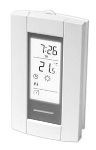


This is a legacy product document supported by Resideo. It is no longer manufactured

Need Help?
We are here to help. Call 1-800-831-2823.
Before you start
Read the entire document
CAUTION:
- Installation must be carried out by a certified electrician and must comply with national and local electrical codes.
- Use this thermostat for resistive loads only.
- Do NOT install the thermostat in an area where it can be exposed to water or rain.
- To prevent severe shock or electrocution, always turn the power Off at the service panel before working with the wiring.
- Install the thermostat onto an electrical box.
- Use special CO/ALR solderless connectors if you connect the thermostat to aluminum wires.
- Keep the thermostat’s top and bottom air vents (openings) clean and unobstructed at all times.
About your thermostat
The TH115 programmable thermostat has three temperature control modes:
A mode: controls the ambient air temperature
F mode: controls the floor temperature using an external temperature sensor
AF mode: controls the ambient air temperature
maintains the floor temperature within desired limits using an external temperature sensor
See page 9 on how to change the temperature control mode setting.
Supplied Parts
- One (1) thermostat
- Two (2) mounting screws
- Four (4) solderless connectors for copper wires
- One (1) floor sensor
- One (1) flat-tip screwdriver
Controls

*Place at Off to cut power to the heater (e.g., in the summer). This will not affect the time and temperature settings.
**When the backlight button or either of the

Display

* The thermostat normally displays the actual (measured) temperature. To view the setpoint temperature, briefly press either of the
Installing the thermostat
- Turn the heating system off at the main electrical panel.
- Loosen the bottom screw and remove the thermostat faceplate from its
wallplate. (The screw cannot be completely removed.) - Connect the thermostat to the load and to the power supply (see page 7).
- Connect the floor sensor (see page 8).
- If you wish to connect a remote control device, see page 8.
- Install the wall plate to the electrical box using the provided screws.
- Set the configuration switches on the back of the faceplate (see page 9).
- Install the faceplate back on the wall plate and tighten the screw.
- Apply power to the heating system.
- Test the ground fault protection (see page 19).

Wiring diagram
NOTE: Connect the wires using the provided solderless connectors for copper wires.

Connecting the floor sensor / remote control
- Insert the floor sensor cable through one of the two openings on the wall plate and connect the sensor wires to terminals 1 and 2 (no polarity).
• The sensor cable must not come in contact with the electrical wires and must be routed outside the electrical box and follow the wall down to the floor.
• Position the sensor cable such that it does not come in contact with the floor heating wires. The sensor must be centered between two-floor heating wires for the best temperature control.
• Do NOT staple the sensor head (the plastic end) to the floor. Doing so might damage the sensor. Any damage might not be noticeable during testing but can become apparent several days later. - If you wish to connect a remote control device (see page 17), insert the wires (use 18- to 22-gauge flexible wires) through one of the two openings on the wall plate and connect them to terminals 2 and 3 (no polarity).

Set the configuration switches
Configuration switches are on the back of the faceplate.
| # | Configurations | Up | Down |
| 1 | Display format | °F / 12 h | °C / 24 h |
| 2 | Early Start | Enable | Disable |
| 3 | Temperature control model | F | AF |

- Early Start is used in Automatic mode only. When Early Start is enabled (on), the thermostat determines when to start heating so the Comfort temperature is attained at the beginning of periods 1 and 3. When Early Start is disabled (off), heating starts only at the beginning of periods 1 and 3; thus there is a delay before the Comfort temperature is reached.
- See page 3. To select the F Mode, place the switch in the F position. To select the AF Mode, place the switch in the AF position and ensure that the temperature sensor is connected to the thermostat. To select the A Mode, place the switch in the AF position and ensure that the remote temperature sensor is NOT connected to the thermostat.
Time and day
To set the clock and the day:
- Press the Hour button to set the hour.
- Press the Min button to set the minutes.
- Press the Day button to set the day.
- Press the Mode/Ret button to return the thermostat to a normal display.
NOTE: The thermostat will automatically return to normal display if no button is pressed for 60 seconds.
Daylight Saving Time
When the Daylight Saving Time function is enabled (On), the thermostat automatically switches to Daylight Saving Time on the second Sunday of March and to normal time on the first Sunday of November.
NOTE: The Daylight Saving Time function is disabled (default setting) when the clock loses its setting.
To set the Daylight Saving Time function and to set the date:
- Press the Day button (3 seconds) until DLS appears on the screen.
- Press either of the
- Press the Day button briefly. The year setting is displayed.
- Press either of the
- Press the Day button briefly. The month setting is displayed.
- Press either of the
- Press the Day button briefly. The date setting is displayed.
- Press either of the
- Press the Mode/Ret button to return the thermostat to a normal display.
NOTE: The thermostat will automatically return to normal display if no button is pressed for 60 seconds.
Floor temperature limits (AF mode only)
WARNING: To avoid damaging your floor, follow your floor supplier’s recommendations regarding floor temperature limits.
The minimum and maximum floor temperature limits are 5.0°C (41°F) and 28.0°C (82°F) by default.
To modify these limits, proceed as follows:
- Switch the thermostat to Off.
- Press and hold the
- Switch the thermostat back to On.
- Release the
- Set the minimum temperature limit using the
- Press the
- Set the maximum temperature limit using the
- Press Mode/Ret to return the thermostat to the normal display.


NOTE: The thermostat will automatically return to normal display if no button is pressed for 60 seconds.
Preset temperatures
The thermostat has 3 preset temperatures. Their default settings are shown in the following table.
| Preset temperature | Intended use | Icon | A/AF modes | F mode |
| Comfort | When at home | 21.0°C (70°F) | 28.0°C (82°F) | |
| Economy | When asleep or away from home | 17.0°C (63°F) | 20.0°C (68°F) | |
| Vacation | During prolonged absence | 10.0°C (50°F) | 10.0°C (50°F) |


To use a preset temperature:
Briefly press the appropriate preset temperature button (
become the current setpoint and its icon will appear on the screen.
To modify a preset temperature:
- Press one of the
- Press and hold the appropriate preset temperature button (
Default schedule
The schedule consists of 4 periods per day, which represents a typical workday. The Comfort (


NOTE: If you wish to use only 2 periods, use the following combinations: “1 and 4” or “2 and 3”. Early Start (see page 9) will not work with any other combinations.
You can have a different program every day; i.e., each period can start at a different time every day. The thermostat has been programmed with the following schedule.
| Period | Description | Setting | MO | TU | WE | TH | FR | SA | SU |
| Wake | Comfort – |
6:00 | 6:00 | 6:00 | 6:00 | 6:00 | 6:00 | 6:00 | |
| Leave | Economy |
8:30 | 8:30 | 8:30 | 8:30 | 8:30 | –:– | –:– | |
| Return | Comfort – |
17:00 | 17:00 | 17:00 | 17:00 | 17:00 | –:– | –:– | |
| Sleep | Economy |
23:00 | 23:00 | 23:00 | 23:00 | 23:00 | 23:00 | 23:00 |


Modifying the schedule
- Press PGM. Period 1 for Monday is displayed.
- To program another period, press Pgm to display that period.
- To program another day, press Day to display that day (hold for 3 seconds to select the entire week).
- Press Hour and Min to set the period start time or press Clear to skip (cancel) the period (–:– will be displayed).
- Repeat steps 2 to 4 to program another period.
- Press Mode/Ret to return the thermostat to the normal display.
NOTE: The thermostat will automatically return to normal display if no button is pressed for 60 seconds.
Running the schedule (Automatic mode)
In Automatic mode, the thermostat follows the programmed schedule (see

Temporary override of schedule
If you modify the setpoint temperature (by pressing the
Permanent override of schedule (Manual mode)
To place the thermostat in Manual mode, press Mode/Ret to display

When you go on vacation (Vacation mode)
In this mode, the thermostat uses the vacation preset temperature (see page 13). There are two ways to place the thermostat in Vacation mode:
- Press the
- From any remote control device equipped with a dry contact. When the contact closes, the thermostat is placed in Vacation mode and
the
NOTE: When the Vacation mode is activated from a remote control device, it can only be deactivated using the device.
Ground fault protection (GFCI)
This ground fault protection thermostat is different from conventional thermostats. In the event of a ground fault, the ground fault protection mechanism on the thermostat will trip and quickly stop the flow of electricity to prevent serious injury.
Definition of a ground fault
Instead of following its normal safe path, electricity passes through a person’s body to reach the ground.
For example, a defective floor heating mat can cause a ground fault.
A ground fault protection thermostat does not protect against circuit overloads, short circuits, or electrical shocks. For example, you can still receive an electrical shock if you touch bare wires while standing on a non-conducting surface such as a wood floor.
Ground fault protection reset
When the ground fault protection mechanism trips, the TEST light is On (red). To reset the ground fault protection, switch the thermostat to Off and back to On. The TEST light will turn off.
Testing the ground fault protection
To ensure the ground fault protection is always in working order, test it once the thermostat is installed and on a monthly basis thereafter.
- Increase the setpoint temperature above the measured temperature in order to activate the heating system.
- Press the TEST button.
• If the TEST light does NOT turn on, the test has failed. Cut power to the heating system at the main electrical panel, have an electrician verify the installation and, if necessary, replace the thermostat.
• If the TEST light turns on, continue the test. - Switch the thermostat to Off then back to On.
• If the TEST light turns off, the test has passed. Set the thermostat back to the desired temperature. ture. The test is now completed.
• If the TEST light remains on, the test has failed. Continue with the rest of the procedure. - Switch the circuit breaker (at the service panel) of the heating system to off then back to on.
- Repeat the test. If the test fails again, cut power to the heating system at the main electrical panel, have an electrician verify the installation and, if necessary, replace the thermostat.

Error Messages


Technical Specifications
| Model | Supply | Max. load (resistive only) | Ground Fault
Protection (GFCI) |
Wiring | |
| Current | Power | ||||
| TH115-AF-GA | 120 VAC, 60 Hz | 15 A | 1800 W | 5 mA | 4 wires, double pole |
| 240 VAC, 60 Hz | 3600 W | ||||
| TH115-AF-GB | 120 VAC, 60 Hz | 1800 W | 15 mA | ||
| 240 VAC, 60 Hz | 3600 W | ||||
Display range: 0°C to 70.0°C (32°F to 158°F)
Ambient setpoint range (A/AF modes): 5.0°C to 30.0°C (40°F – 86°F)
Floor setpoint range (F mode): 5.0°C to 40.0°C (40°F – 104°F)
Floor limit range (AF mode): 5.0°C to 40.0°C (40°F – 104°F)
Resolution: 0.5°C (1°F)
Heating cycle length: 15 minutes
Data protection: In the event of a power failure, most settings are saved. However, the time and Daylight Saving Time must be set if the power failure lasts more than 6 hours. The thermostat will return to the mode that was active prior to the power failure.
Customer Assistance
If you have any questions about the product installation or operation, contact us at:
705 Montrichard
Saint-Jean-sur-Richelieu, Quebec
J2X 5K8
Canada
Tel.: 1-800-831-2823
Fax: (450) 358-4650
Email: aube.
Warranty
Honeywell warrants this product, excluding battery, to be free from defects in the workmanship or materials, under normal use and service, for a period of three (3) years from the date of purchase by the consumer. If at any time during the warranty period the product is determined to be defective or malfunction, Honeywell shall repair or replace it (at Honeywell’s option).
If the product is defective,
- return it, with a bill of sale or other dated proof of purchase, to the place from which you purchased it, or
- contact Honeywell. Honeywell will make the determination whether the product should be returned, or whether a replacement product can be sent to you.
This warranty does not cover removal or reinstallation costs. This warranty shall not apply if it is shown by Honeywell that the defect or malfunction was caused by damage that occurred while the product was in the possession of a consumer.
Honeywell’s sole responsibility shall be to repair or replace the product within the terms stated above. HONEYWELL SHALL NOT BE LIABLE FOR ANY LOSS OR DAMAGE OF ANY KIND, INCLUDING ANY INCIDENTAL OR CONSEQUENTIAL DAMAGES RESULTING, DIRECTLY OR INDIRECTLY, FROM ANY BREACH OF ANY WARRANTY, EXPRESS OR IMPLIED, OR ANY OTHER FAILURE OF THIS PRODUCT. Some provinces, states, or regions do not allow the exclusion or limitation of incidental or consequential damages, so this limitation may not apply to you.
THIS WARRANTY IS THE ONLY EXPRESS WARRANTY HONEYWELL MAKES ON THIS PRODUCT. THE DURATION OF ANY IMPLIED WARRANTIES, INCLUDING THE WARRANTIES OF MERCHANTABILITY AND FITNESS FOR A PARTICULAR PURPOSE, IS HEREBY LIMITED TO THE THREE-YEAR DURATION OF THIS WARRANTY. Some pros-
inches, states, or regions do not allow limitations on how long an implied warranty lasts, so the above limitation may not apply to you.
This warranty gives you specific legal rights, and you may have other rights which vary from one province, state, or region to another.