Motorola Visor-Mounted Microphone RMN5054 User Guide


MOTOROLA Visor-Mounted Microphone RMN5054

Product Safety and RF Exposure Compliance
CAUTION: Before using this product, read the operating instructions for safety usage contained in the Product Safety and RF Exposure booklet enclosed with your radio.
ATTENTION!
The Visor-Mounted Microphone, when attached to the mobile radio, is restricted to occupational use only to satisfy FCC RF energy exposure requirements. Before using this product, read the RF energy awareness information and operating instructions in the Product Safety and RF Exposure booklet enclosed with your radio to ensure compliance with RF energy exposure limits.
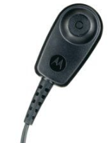
DESCRIPTION
The RMN5054 Visor-Mounted Microphone facilitates hands-free microphone use with the mobile radio. All necessary hardware to install the microphone is supplied with the RMN5054 kit.
The below Push-To-Talk (PTT) devices are available for use with the RMN5054
Visor-Mounted Microphone:
- Push Button PTT RLN5926
- Footswitch PTT GLN7278
(For APX™ radios only)
These PTT devices are available separately and include installation instructions.
INSTALLATION
Carefully select the installation location for the RMN5054 Visor-Mounted Microphone.
To achieve optimum performance of the microphone’s hands-free circuitry, mount the microphone in one of the following two locations:
- on the sun-visor directly above the driver or
- on the headliner just above the driver.
The microphone should never be mounted near the window or in a place where the road and ambient background noise would be substantially high (above 85 dB SPL).

Visor Mounting (Figure 1)
1. Slide the mounting clip onto the back of the microphone.
2. Slide the mounting clip/visor microphone onto the top of the sun-visor.
Headliner Mounting (Figure 2)
- For the most secure mount, adhere the Velcro inside the vehicle at a temperature of about 73°F (23°C).
- Choose the desired location and position of the Velcro so that the microphone ports face the operator when attached.
- Remove the adhesive backing from the flexible Velcro strip and adhere the strip to the desired location. To ensure maximum adhesion, leave the Velcro strip undisturbed for 24 hours before use.
- Remove the metal clip and replace it with the plastic plate with Velcro.
- Slide the Velcro strip between the guides on the back of the microphone until it snaps into place.
- Mount the microphone by pressing the two Velcro surfaces together.

Cable Routing
Refer to the applicable mobile radio Installation manual for instructions on remote connection cable routing.
Connecting to the Mobile Radio
The Visor-Mounted Microphone cable connects to a 26-pin connector block (supplied with radio).
The connector block can either be in the shape of a rectangle (MOTOTRBO™ and TETRA MTM5000/MTM800 series radios) or trapezoid (APX series radios). Refer to Figures 3, 4, 5, and 6.
MOTOTRBO Installation
Using the appropriate tools, crimp the 3 shorter pins supplied with the kit to the stripped ends of the Visor-Mounted Microphone wires.
Insert the wires into the back of the connector block as follows.
White wire connects to one of the following pins (in preferred order) 4, 12, 8, 16, or 18;
Red wire connects to pin 11 and,
Blue wire connects to pin 5 or 6.
The connector block plugs into the rear accessory connector on the back of the mobile radio.

MTM5200, MTM5400, MTM5500, MTM800FuG and MTM800FuG ET Rear Accessory Connector Installation
Using the appropriate tools, crimp the 3 shorter pins supplied with the kit to the stripped ends of the Visor-Mounted Microphone wires.
Insert the wires into the back of the 26 way connector block as follows.
White wire connects to pin 16;
Red wire connects to pin 13 and;
Blue wire connects to pin 5.
The connector block plugs into the rear accessory connector on the back of the mobile.

APX Installation
Using the appropriate tools, crimp the 3 longer, narrow pins supplied with the kit to the stripped ends of the Visor-Mounted Microphone wires.
Disassemble the connector block as shown in Figure 5 by removing the two Phillips head screws.

Insert the wires into the back of the connector block as follows.
Note: Do not remove the jumper wire that is installed between pins 14 and 15 unless emergency accessory is being installed.
White wire connects to pin 1;
Red wire connects to pin 23 and;
Blue wire connects to pin 17.

Reassemble the connector block, and install it into the rear accessory connector on the back of the mobile radio.
SERVICE
The RMN5054 Visor-Mounted Microphone is not repairable. Order a replacement microphone as necessary.
MOTOROLA, MOTO, MOTOROLA SOLUTIONS and the Stylized M logo are trademarks or registered trademarks of Motorola Trademark Holdings, LLC and are used under license. All other trademarks are the property of their respective owners.
© 2006 and 2020 Motorola Solutions, Inc. All rights reserved.
MOTOROLA, MOTO, MOTOROLA SOLUTIONS and the Stylized M logo are trademarks or registered trademarks of Motorola Trademark Holdings, LLC and are used under license. All other trademarks are the property of their respective owners.
© 2006 and 2020 Motorola Solutions, Inc.
All rights reserved.
