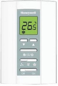
Honeywell T6812A1000 Digital Thermostat Installation Guide
Honeywell T6812A1000 Digital Thermostat Installation Guide


Disconnect power before removing cover.

Terminal Designations
| Terminal | Description |
L |
Live |
Ch/Cc |
Heating close / Cooling close |
W/Y |
Heating open / Cooling open |
N |
Neutral |
GI |
Low fan speed |
Gm |
Medium fan speed |
Gh |
High fan speed |
Wiring

- Typical wiring for ON / OFF control in 2 pipe systems (VC4 valves)
- Typical wiring for ON / OFF control in 2 pipe systems (VC6 valves)


Thermostat Installation

Installer Parameters Table
| N o | Parameter | Setting |
| 1 | System type | 0 = 2 pipe system, heat only |
| 1 = 2 pipe system, cool only | ||
| 2 = 2 pipe system, heat or cool, manual changeover (default) | ||
| 9 | Temperature Scale | 0 = °F |
| 1 = °C (default) | ||
| 13 | Cycles Per Hour value for HEATING |
1 – 12 (default = 4) |
| 14 | Cycles Per Hour value for COOLING |
1 – 6 (default = 3) |
| 18 | Temperature display offset | -2.0°C to +2.0°C increment 0.5°C / -4°F to +4°F increment 1.0°F (default = 0°) |
| 19 | Temperature display mode | 0 = Display room temperature (default) |
| 1 = Display setpoint | ||
| 20 | Heating range stops | 10 – 32°C (default maximum
= 32°C) / 50 – 90°F (default maximum = 90°F) |
| 21 | Cooling range stops | 10 – 32ºC (default minimum = 10ºC) / 50 – 90ºF (default minimum
= 50ºF) |
| 22 | Keypad lockout | 0 = All keys available (default) |
| 1 = All keys locked |
Was this manual helpful?
Thank you for your feedback!