GE Quadcore HD Antenna User Manual

Antenna
User Manual


YOU MUST PERFORM A CHANNEL SCAN AFTER INSTALLATION.
SE REFER TO YOUR MANUAL FOR SCAN INSTRUCTIONS OR CALL TV MANUFACTURER.

Questions? Contact our U.S.-based
Consumer Care at 1-800-654-8483
between 7 AM-8 PM, M-F, Central Time.
See reverse for easy-to-follow instructions and exclusive deals.
WARNING: INSTALLATION OF THIS PRODUCT NEAR POWER LINES IS DANGEROUS. FOR YOUR SAFETY, FOLLOW THE INSTALLATION DIRECTIONS.

Instructions made easy

Read instructions or watch the easy-to-follow videos. Scan code or visit byjasco.com/48896i
IMPORTANT SAFETY INSTRUCTIONS:
- NEVER touch ANYTHING or ANYONE in contact with a power line. You can be electrocuted. In case of an accident or emergency, call 911 immediately for help.
- INSPECT your installation site carefully for power lines. Make sure there is no possibility the antenna, its mounting structure, or your ladder can contact power lines. Consider what can go wrong during installation.
- KEEP the distance between power lines and the antenna and its mounting structure at least twice the combined height of the antenna and mounting structure added together. In the event the antenna falls during or after assembly, there must be sufficient distance to ensure it does not contact the power lines.
- KEEP your ladder, the antenna, and antenna mounting structure (such as mast, pole, and mount) far away from power lines at all times.
- GROUND the antenna and the antenna mounting structure in accordance with the NEC electrical code, all state, and local electrical code requirements.
- COMPLETE the antenna assembly on the ground.
- DO NOT use a metal ladder or install the antenna on a windy day. If the antenna or mast starts to fall, do not attempt to catch the antenna.
- EXERCISE caution when working on a roof.
- APPLY the included danger label to the base of the antenna mounting structure.
- INFORM others of the danger of touching power lines or touching other objects in contact with power lines.
- CONTACT a professional installer to install the antenna if you are unsure how to safely install and ground this antenna.
- DO NOT use the power inserter and power supply outdoors. They are rated for indoor use only. Use only the power supply provided with the antenna.
SELECT AND MEASURE YOUR INSTALLATION SITE
When selecting the antenna installation site:
- Choose a SAFE location far away from power lines. Keep the distance between power lines and the antenna and its mounting structure at least 2 times the combined height of the antenna and its mounting structure. Refer to the Important Safety Instructions.
- Determine the location of the broadcast towers in your area so you can face the antenna elements toward those towers. Online resources, such as www.antennaweb.org and www.dtv.gov can help identify the location of broadcast towers in your area and the channels you can expect to receive.
- Check your local city and state building and electrical codes. Make sure your planned installation is safe and in compliance with all applicable codes, rules, and regulations.
IF YOU ARE UNSURE OR DO NOT FEEL CAPABLE OF INSTALLING THIS ANTENNA,
CONTACT A PROFESSIONAL INSTALLER.
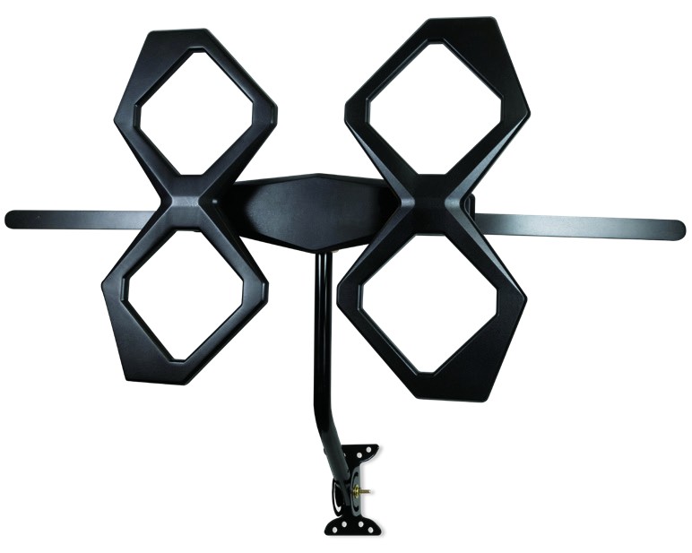
Thank you for purchasing the GE branded Outdoor Quadcore HD Antenna. This sturdy, high-performance antenna is designed to receive UHF and VHF broadcast signals. Its compact design allows you to install it almost anywhere on your home’s exterior.
PARTS LIST:
| 1 | Antenna elements (x2) | |
| 2 | Main housing unit (x1) | |
| 3 | M5 X 50mm bolts (x4) | |
| 4 | VHF dipoles (x2) | |
| 5 | M3 X 8mm bolts (x4) | |
| 6 | M5 X 12mm bolts (x2) | |
| 7 | Backplate (x1) | |
| 8 | U-bolt and clamp assembly (x1) a. Clamp (x1) b. U-bolt (x1) c. Wing nuts (x2) |
|
| 9 | Mounting bracket (x1) | |
| 10 | J-mount (15/16in. or 2/5cm) (x1) | |
| 11 | 2in. X 50.8mm lag screws (x4) | |
| 12 | M6 X 50mm bolts (x2) | |
| 13 | M6 locking nuts (x2) | |
| 14 | M6 washers (x4) | |
| 15 | M5 X 40mm bolts (x1) | |
| 16 | M5 nut (x1) | |
| 17 | Rubber boot (x1) | |
| 18 | Small zip tie (x1) | |
| 19 | Large zip tie (x2) | |
| 20 | Danger label (x1) | You can be KILLED if this product comes near electric power lines. |


ASSEMBLING THE ANTENNA:
- Connecting the Antenna Elements to the Main Housing Unit
a. Connect each antenna element to the main housing unit by inserting the housing unit’s round protrusions into the round groove on each antenna element (Fig. 1a, Fig. 1b & Fig. 1c). - Connecting the VHF Dipoles
Place the VHF dipoles in the matching grooves on the back of the main housing unit, making sure the side of each dipole marked “THIS SIDE UP” is facing upward. Secure the dipoles with M3 X 8mm bolts (Fig. 2a & Fig. 2b). - Attaching the U-bolt and Clamp Assembly to the Main Housing Unit
Place the middle of the U-bolt in the groove of the metal backplate and align the holes on the backplate with the holes on the main housing unit. Secure the U-bolt in place with M5 X 12mm bolts (Fig. 3a & Fig. 3b). - Installing the Assembled Antenna
a. Locate a position on the house that is far away from power lines. Refer to the Important Safety Instructions.
b. Secure the mounting bracket to the location selected or the antenna. The 2in. X 50.8mm lag screws have been provided for some installations.
c. Connect the J-mount to the mounting bracket
(Fig. 4a) using the M6 X 50mm bolts, M6 locking nuts, and M6 washers.
e. Slide the antenna onto the J-mount (Fig. 4b). Face the antenna elements toward the broadcast towers in your area. Tighten the wing nuts on the U-bolt when the antenna is in the desired position.


ANTENNA GROUNDING & CONNECTION
The National Electric Code (NEC) requires your outdoor antenna installation to be properly grounded. This involves grounding the antenna and the antenna mounting structure. This helps protect you and your property in the event of static buildup on the antenna or lightning near your home.
NOTE: If you had a satellite or cable system installed at your home, you may be able to use some parts from this system for your antenna installation.
- Ground the Antenna Mount: Attach a #8 aluminum or a #10 copper grounding wire to the antenna mounting structure, such as a pole, mast, tower, etc. In some cases, a bolt on the mount can be used for making this connection. When using the provided J-mount, use the M5 bolt and M5 nut in the hole on the J-mount located above the mounting bracket to make this connection (Fig. 5a).
- Connect the Antenna: Use an outdoor-rated coax cable to connect the antenna to the 75-ohm grounding block (not provided). Fig. 5b is an example of a 75-ohm grounding block. Verify that the grounding block is properly grounded. See Grounding Block How-To.
If you are using a pre-built cable with connectors, follow these steps.
a. Cut four slits spaced evenly apart at the narrow tip of the provided rubber boot, approximately 1/4in. in length (Fig. 5c).
c. Slide the rubber boot into the round channel on the main housing unit.
d. Wrap the small zip tie around the slits in the narrow end of the rubber boot and pull it tight.
From the grounding block, connect an in-wall rated coax cable that will run through the wall into your home to an interior cable wallplate connection or, for whole-home installation, a coaxial splitter in your attic. A separate in-wall rated coax cable running to a separate cable wallplate is required for each location served by the splitter. The 75-ohm grounding block needs to be placed as close as possible to the point where the second coax cable enters your home.
NOTE: Be sure to leave enough slack in the coax cable to create a drip loop so moisture cannot enter your house. You will also need to seal the coax cable entry point into your house with exterior caulk.
NOTE: Use of multiple splitters in a whole-home installation will seriously degrade signal quality and is not recommended. - Connect your TV’s antenna port to the coax wall plate using a coaxial cable.
- Follow your HDTV’s instruction manual to scan for channels on your TV.


Grounding Block How-To:
Your existing outdoor antenna should already have a properly installed grounding block in place, but if it must be moved or is improperly grounded, please follow these important instructions to ensure your antenna is safely grounded.
- Connect a #8 aluminum or #10 grounding wire to a screw terminal on the 75-OHM grounding block.
- Connect the other end of the wire to an acceptable building ground location. See examples below.
Examples of acceptable building grounding locations are:
• The building or structure grounding electrode system as covered in 250.50 in the NEC
• Grounded interior metal water piping system within 5ft. from its point of entry to the building
• Grounded, non-flexible metallic power service raceway
• Service equipment enclosure, the grounding electrode conductor or the grounding electrode conductor metal the enclosure of the power service
• An 8ft. grounding rod driven into the ground can be used as long as it is connected to the central building ground by a #6 or heavier bonding wire.
Refer to the NEC sections 250 and 810 for other acceptable grounding methods.
Double-check all your connections after installation is complete. Ensure there are good electrical connections to your grounding wires and coax cables. See Fig. 5d for an example of a properly grounded antenna installation.

ANTENNA REMOVAL
Inspect the area carefully for power lines. Look for any new power lines that may have been installed. Make sure there is no possibility the antenna, its mounting structure, or your ladder can contact power lines. Consider what can go wrong during the antenna removal. Repeat the steps for antenna installation in reverse order.
ANTENNA HELPFUL TIPS
Maximize the number of channels by testing the antenna in several locations. Be sure to run a TV channel scan in each position. Refer to your TV’s instruction manual if necessary.
For best performance, position or mount the antenna as high as possible facing the broadcast towers.
Visit www.antennaweb.org or www.dtv.gov to determine the available television stations and broadcast tower locations in your area.
QUESTIONS? ISSUES?
CALL OUR U.S.-BASED EXPERTS AT 1-800-654-8483
MADE IN CHINA
GE is a trademark of General Electric Company and is under license by Jasco Products Company LLC, 10 E.
Memorial Rd., Oklahoma City, OK 73114.
This Jasco product comes with a limited lifetime warranty. Visit www.byjasco.com for warranty details.
Questions? Contact our U.S.-based Consumer Care at1-800-654-8483 between 7 AM -8 PM Central Time.
48896 V1 6/20