D-Link DXS-3610-54S Layer 3 Stackable 10G Managed Switches User Guide
D-Link DXS-3610-54S Layer 3 Stackable 10G Managed Switches User Guide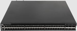

Introduction
This Quick Installation Guide gives instructions for setting up the D-Link DXS-3610-54S switch. The model you have purchased may appear slightly different from those shown in the illustrations. For more detailed information about the device, its components, making network connections and technical specifications, please refer to the User Manual.
Package Contents
- One DXS-3610-54S switch
- Two pre-installed AC power supply modules (DXS-PWR700AC)
- Five pre-installed fan modules with front-to-back-airflow (DXS-FAN200)
- AC power cords
- One RJ45 to RS-232 console cable
- One USB cable
- Four rubber feet with adhesive backing
- One rack mounting kit, containing two brackets and a number of screws
- One quick installation guide
- One Warranty Card
If any item is missing or damaged, please contact your local D-Link reseller for replacement.
Notes and Cautions


Hardware Overview
Front Panel

This following table lists the front panel components on the DXS-3610-54S switch:
| Component | Description |
| SFP+ Ports (1/10 Gbps) | This switch is equipped with 48 SFP+ ports that can operate at 1 and 10 Gbps wire- speeds and support a wide collection of SFP/SFP+ transceivers. |
| QSFP28 Ports (40/100 Gbps) | This switch is equipped with 6 QSFP28 ports that can operate at 40 and 100 Gbps wire-speeds and support a wide collection of QSFP+/QSFP28 transceivers. |
| Console Port | The console port can be used to connect to the CLI of the Switch. This Out-Of-Band (OOB) connection can be made from the serial port of an administrative node to the RJ45 console port on the front panel of the Switch. The console cable (included in the package) must be used for the connection. |
| MGMT Port | The management (MGMT) port can be used to connect to the CLI or the Web UI of the Switch. SNMP-enabled connectivity can also be made through this port. This OOB connection can be made from a standard LAN adapter to the RJ45 MGMT port on the front panel of the Switch. This connection operates at 10/100/1000 Mbps. |
| Micro-USB Port | The micro-USB port provides additional storage space for firmware images and configuration files that can be copied to and from the Switch. Only endpoint devices like USB flash drives are supported. |
| Reset Button | The reset button can be used to reboot the switch or to reset the switch to its factory default settings depending on how long this button is pressed. Press and hold for less than 5 seconds This reboots the Switch. All unsaved configurations will be lost. Press and hold for between 5 and 10 seconds This resets the software configuration on the Switch to the factory default settings. |
| Information Tag | The sliding information tag is discretely located on the front panel, right next to the QSFP28 ports, and contains the product code, hardware version, serial number, and MAC address of the Switch. The QR code can be scanned to quickly obtain the above mentioned information. |
Front Panel LED Indicators
Figure 2. DXS-3610-54S Front Panel LED Indicators

The front panel LED indicators are described in the following table:
| LED | Color | Status | Description |
| Locator | Blue | On (Solid) | User logged in |
| – | Off | Locator function is disabled | |
| Power | Green | On (Solid) | Power on |
| On (Blinking) | Performing system self-test | ||
| Amber | On (Solid) | PSU failed or Voltage/Current/Temperature too high | |
| – | Off | Power off | |
| Status | Green | On (Solid) | POST passed and normal operation |
| On (Blinking) | POST in progress | ||
| Amber | On (Blinking) | POST/PSU/Fan failed or Temperature too high | |
| – | Off | Power off | |
| Fan | Green | On (Solid) | Fan operation normal |
| Amber | On (Blinking) | Fan error | |
| – | Off | Power off | |
| Link/Act (Out-Of-Band port) | Green | On (Solid) | Active connection through the port |
| On (Blinking) | Data transmitted and received through the port | ||
| – | Off | Inactive connection, no link present, or port disabled | |
| Link/Act (10GE SFP+ ports) | Green | On (Solid) | Active connection at 10 Gbps through the port |
| On (Blinking) | Data transmitted and received through the port | ||
| Amber | On (Solid) | Active connection at 1 Gbps through the port | |
| On (Blinking) | Data transmitted and received through the port | ||
| – | Off | Inactive connection, no link present, or port disabled | |
| Link/Act
(100GE QSFP28 ports) |
White (LED 1) | On (Solid) | Active connection at 100 Gbps through the port |
| On (Blinking) | Data transmitted and received through the port | ||
| Blue (LED 4) | On (Solid) | Active connection at 40 Gbps through the port | |
| On (Blinking) | Data transmitted and received through the port | ||
| – | Off | Inactive connection, no link present, or port disabled | |
| Stacking (Master) (100GE QSFP28 ports) | White (LED 1) Amber (LED 2) | On (Solid) | Active connection at 100 Gbps through the port and the Switch is the Master switch in the stack |
| On (Blinking) | Data transmitted and received through the port | ||
| – | Off | No link present | |
| Stacking (Slave) (100GE QSFP28 ports) | Amber (LED 3) Blue (LED 4) | On (Solid) | Active connection at 100 Gbps through the port and the Switch is a Slave switch in the stack |
| On (Blinking) | Data transmitted and received through the port | ||
| – | Off | No link present |
Rear Panel
The rear panel features components like LED indicators, PSU (Power Supply Unit) modules, fan modules and an electrical grounding point. These components are described in detail below.

This following table lists the rear panel components on the Switch:
| Component | Description |
| Switch GND | Use an electrical grounding wire and connect one end of the wire to the switch GND and the other end of the wire to an electrical grounding point most commonly found on the Switch mounting rack itself. |
| Fan Modules | These are five hot-swappable, redundant (4+1) fan module slots on the rear panel of the Switch. The following fan modules can be installed in these slots:
When five fans modules are installed, four fan modules will be active and the fifth fan module will be passive until one of the four active fan modules fail. |
| Power Supply Module Slots | There are two load-sharing power supply module slots on the rear panel of the Switch. The following power supply modules can be installed in these slots:
|
Rear Panel LED Indicators
The LED indicators provide valuable information in a variety of ways like their color, blinking times, and location.

The rear panel LED indicators are described in the following table:
| LED | Color | Status | Description |
| Power Supply Module | Green | On (Solid) | Normal power supply module operation |
| On (Blinking) | PSU module is off but standby power is supplied | ||
| Amber | On (Solid) | PSU/Fan failed or PSU shutdown due to critical event | |
| On (Blinking) | Warning event occurred (Power/Current/Temperature too high or fan is too slow) | ||
| – | Off | Power off or PSU is on but with warning events | |
| Fan Module | Green | On (Solid) | Fan operation is normal |
| On (Blinking) | Fan error occurred | ||
| – | Off | Power off |
Installation
Installing the Switch without a Rack
This section is used to guide the user through installing the Switch in an area other than a switch rack. Attach the included rubber feet to the bottom of the Switch. Take note that there should be marked blocks on the bottom of the Switch to indicate where to attach the rubber feet. These markings are usually found in each corner on the bottom of the device. The rubber feet cushion the Switch, protecting the casing from scratches and preventing it from scratching other surfaces.
Figure 6. Attaching rubber feet to the Switch

Installing the Switch in a Standard 19″ Rack
This section is used to guide the user through installing the Switch into a switch rack. The Switch can be mounted in a standard 19″(1U) rack using the rack mounting kit included in the package contents.
Fasten the frontal rack-mounting brackets to the front-sides of the Switch using the screws provided.
Figure 7. Attaching the frontal rack-mounting brackets

Figure 8. Frontal rack-mounting brackets attached

Slide the rear rack-mounting slider brackets into place, as illustrated below.
Figure 9. Positioning the rear rack-mounting brackets

Fasten the mounting brackets in any available open space in the rack using the screws provided.
Figure 10. Installing the Switch in a Rack

Make sure that there is adequate space around the Switch to allow for proper airflow, ventilation, and cooling.
Installing Transceivers into the Transceiver Ports
The DGS-3610-54S switch is equipped with SFP+ ports and QSFP28 ports.
The figure below illustrates how to properly insert QSFP+/QSFP28 transceivers into the 100GE QSFP28 ports.
Figure 11. Inserting QSFP+/QSFP28 transceivers into the QSFP28 ports

The figure below illustrates how to properly insert SFP/SFP+ transceivers into the 10GE SFP+ ports.
Figure 12. Inserting SFP/SFP+ transceivers into the SFP+ ports

Installing PSU Modules into the PSU Module Slots
The DGS-3610-54S switch supports the installation of AC PSU (Power Supply Unit) modules and/or DC PSU modules into the PSU module slots.
Installing AC PSU Modules
The DGS-3610-54S switch is shipped with two pre-installed AC PSU modules. This section can be referenced when one or more AC PSU modules need to be replaced.
To remove an existing AC PSU module, press the release clip to the side and gently pull the AC PSU module out of the PSU module slot.
Insert the new AC PSU module into the PSU module slot until the release clip securely clicks into place.
Figure 13. Installing an AC PSU Module

Figure 14. Installed AC PSU Module

A second AC PSU module can be installed into the second PSU module slot labelled PSU-2. If the primary AC PSU fails, the second AC PSU is used to provide AC power to the Switch. This takes place immediately and automatically.
When the AC PSU module is securely installed, plug one end of the AC power cord into the AC power socket on the AC PSU module and the other end of the AC power cord into a properly grounded AC power source outlet. There is no power switch/button on the Switch. The system will automatically power on and adjust its power settings to adapt to any voltage supplied within the 100~240VAC range at 50~60Hz.
Installing DC PSU Module
The DGS-3610-54S switch can also be shipped with two pre-installed DC PSU modules. This section can be referenced when one or more DC PSU modules need to be replaced.
Switch and that the Switch is not receiving any power. The power, fan, and other LED indicators must be off.
To remove an existing DC PSU module, press the release clip to the side and gently pull the DC PSU module out of the power supply module slot.
Insert the new DC PSU module into the power supply module slot until the release clip securely clicks into place.
Figure 15. Installing a DC PSU Module


Figure 16. Installed DC PSU Module
A second DC PSU module can be installed into the second PSU module slot labelled PSU-2. If the primary DC PSU fails, the second DC PSU is used to provide DC power to the Switch. This takes place immediately and automatically.
When the DC PSU module is securely installed, insert the one end of the DC power cord, with the plug, into the matching DC power socket on the DC PSU module and the other end of the DC power cord to the DC power source (-48VDC/5.2A). Make sure that the connection polarity (positive and negative) is correct to avoid any damaged.
Figure 17. Connecting a DC Battery to the DC Power Supply Module

There is no power switch/button on the Switch. The Switch will power on automatically.
Installing Fan Modules into the Fan Module Slots
This section guides the user through installing fan modules into the fan module slots. On the rear panel of the DGS-3610-54S switch, there are five fan module slots. Front-to-Back (FB) or Back-to-Front (BF) fan modules can be installed in these slots. By default, the Switch is shipped with five DXS-FAN200 modules pre-installed.
To remove an existing fan module, use a flat-head screwdriver to unscrew the lag bolt (with a slot drive head) and gently pull the fan module out of the fan module slot.
Insert the new fan module into the fan module slot and fasten the lag bolt to secure the fan module into place.
Figure 18. Installing a Fan Module

Figure 19. Installed Fan Module

Switch Connections
Stacking the Switch
The DGS-3610-54S switch supports stacking up to 12 switches together while being managed through one console connection or MGMT connection on the master switch or through any of the RJ45/SFP+/QSFP28 ports using Telnet, the Web UI, and SNMP.
The following stacking topologies are supported on the Switch:
- Duplex Chain ‒ This topology stacks switches together in a chain-link format. Using this method, data transfer is only possible in one direction. If there is a break in the chain, data transfer will be affected.
- Duplex Ring ‒ This topology stacks switches in a ring or circle format where data can be transferred in two directions. It is very resilient due to the fact that, if there is a break in the ring, data can still be transferred through the stacking cables between switches in the stack using the alternate path.
In the following diagram, switches are stacked in the Duplex Chain topology.
Figure 20. Duplex Chain Stacking Topology

In the following diagram, switches are stacked in the Duplex Ring topology.
Figure 21. Duplex Ring Stacking Topology

Switch to Switch
The DGS-3610-54S switch can be used to connect to any other switch or hub in the network. This network topology is used when the Switch does not have enough ports to cater for all the end nodes in the network.
There is a great deal of flexibility on how connections are made using the appropriate cabling.
- Connect a 1000BASE-T switch port to the Switch via a Category 5e UTP/STP cable.
- Connect a 10GBASE-T switch port to the Switch via a Category 6/6a/7 UTP/STP cable.
- Connect a fiber uplink switch port to the Switch’s SFP+/QSFP28 port via a fiber optical cable.
Figure 22. Switch to another Switch/Hub

Switch to Server
The DGS-3610-54S switch is ideal for connecting to a network backbone, server, or server farm. The RJ45 ports operate at speeds of 1/10 Gbps, the SFP+ ports operate at speeds of 1/10 Gbps, and the QSFP28 ports operate at speeds of 10/25/40/50/100 Gbps.
Figure 23. Switch to a Server

Switch to End Node
An end node is a generic name for edge networking devices that will be connected to this switch. Typical examples of end nodes are Personal Computers (PCs), Notebooks, Access Points, Print Servers, VoIP Phones and more. Each end node should be fitted with an RJ45 networking port. Normally, end nodes will connect to this switch by using a standard twisted-pair UTP/STP network cable. When a successful connection is established, the corresponding port light will illuminate and blink to indicate that network activity is taking place on that port.
The diagram below display a typical end node connected to the Switch.
Figure 24. Switch to End Node

Switch Management
Command Line Interface (CLI)
The CLI provides access to all of the software features available on the Switch. These features can be enabled, configured, disabled, or monitored by simply entering the appropriate command after the CLI prompt and pressing the Enter key. The Console port offers an Out-Of-Band (OOB) connection to the CLI and the LAN ports offers an in-band connection to the CLI using Telnet or SSH.
Connecting to the Console Port
The Console port is used to connect to the CLI of the Switch. Connect the DB9 connector of the console cable (included in the packaging) to the Serial (COM) port of the computer. Connect the RJ45 connector of the console cable to the Console port on the Switch.
To access the CLI through the Console port, Terminal Emulation Software must be used like PuTTY or Tera
Term. The Switch uses a connection of 115200 bits per second with no flow control enabled.
Figure 25. Console Connection Settings

After the boot sequence completed, the CLI login screen is displayed.
Logging into the CLI
At the login screen, enter the Username and Password and press Enter after each entry to access the CLI.

username and password for this Switch.
Creating a User Account
To create a new user account, use the username command in the Global Configuration Mode.

A user account with the username ‘NewUser’, password ‘12345’, and privilege level 15 was created.
To configure the IP address of the Switch, use the ip address command in the VLAN Interface Configuration Mode.

The IP address of the Switch was change to ‘10.50.50.50’ with the subnet mask of ‘255.0.0.0’
Web User Interface (Web UI)
The Web UI, a more graphical representation, provides access to most of the software features available on the Switch. These features can be enabled, configured, disabled, or monitored using any standard web browser, like Microsoft’s Internet Explorer, Mozilla Firefox, Google Chrome, or Safari. The LAN ports offers an in-band connection to the Web UI using HTTP or HTTPS (SSL).
Connecting to the Web UI
To access the Web UI, open a standard web browser, enter the IP address of the Switch into the address bar of the browser, and press the Enter key.

The default username and password is admin.
Logging into the Web UI
In the authentication window, enter the User Name and Password and click the Login button to access the Web UI.

SNMP-based Management
The DGS-3610-54S switch can be managed with an SNMP-compatible console program. The Switch supports Simple Network Management Protocol (SNMP) versions 1, 2c, and 3. An SNMP agent decodes the incoming SNMP messages and responds to requests with MIB objects stored in the database. The SNMP agent updates the MIB objects to generate statistics and counters.
Connecting using SNMP
In SNMP versions 1 and 2c, user authentication is accomplished using community strings, which function like passwords. The remote user SNMP application and the Switch must use the same community string. SNMP packets from any station that were not authenticated are ignored (dropped).
The default community strings for the Switch are:
- public – Allows authorized management stations to retrieve MIB objects.
- private – Allows authorized management stations to retrieve and modify MIB objects.
SNMPv3 uses a more sophisticated authentication process that is separated into two parts. The first part is to maintain a list of users and their attributes that are allowed to act as SNMP managers. The second part describes what each user on that list can do as an SNMP manager.
The Switch allows groups of users to be listed and configured with a shared set of privileges. This SNMP version may also be set for a listed group of SNMP managers. Thus, a group of SNMP managers can be created to view read-only information or receive traps using SNMP version 1, while assigning a higher level of security to another group, granting read/write privileges using SNMP version 3.
Using SNMP version 3 individual users or groups of SNMP managers can be allowed to perform or be restricted from performing specific SNMP management functions. The functions that have been allowed or restricted are defined using the Object Identifier (OID) associated with a specific MIB. An additional layer of security is available for SNMP version 3 in that SNMP messages may be encrypted.
Traps
Traps are messages that are sent by an SNMP-enabled device to the Network Management Station (NMS) and can be used to alert network personnel of events that occur on the Switch. These events can be as serious, like a reboot (someone accidentally turned off the Switch), or less serious like a port status change. The Switch generates traps and sends them to a pre-configured IP address, usually an NMS. Typical traps include trap messages for Authentication Failure and Topology Change.
Management Information Base (MIB)
A MIB stores management and counter information. The Switch uses the standard MIB-II Management Information Base module. Consequently, values for MIB objects can be retrieved from any SNMP-based network management software. In addition to the standard MIB-II, the Switch also supports its own proprietary enterprise MIB as an extended Management Information Base. The proprietary MIB may also be retrieved by specifying the MIB Object Identifier. MIB values can be either read-only or read-write.