D-Link DGS-3000-28SC Layer 2 Gigabit Stackable Managed Switch Installation Guide

20-port 100/1000Base-X SFP, 4-port 100/1000Base-T/SFP combo and
4-port 10GBase-X SFP+ Stackable Managed L2 Switch /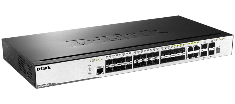


Introduction
This Quick Installation Guide gives instructions for setting up the D-Link DGS-3000-28SC switch. The model you have purchased may appear slightly different from those shown in the illustrations.
Package Contents
Open the shipping carton of the Switch and carefully unpack its contents. Please consult the packing list located to make sure all items are present and undamaged.
|
|
If any of the above items are damaged or missing, please contact your local reseller for replacement.
Hardware Overview
LED Indicators

| LED | Colour | Status | Description |
| Power | Green | Solid Green | Power on. |
| Light Off | Power off. | ||
| Console | Green | Blinking Green | During the Power-On Self Test (POST). |
| Light Off | The Power-On Self Test (POST) is finished. | ||
| Solid Green | A user is logged in through the console port. | ||
| RPS | Green | Solid Green | RPS is connected. |
| Light Off | RPS is not connected / RPS switch is turned off. | ||
| Fan Err | Red | Blinking Red | Any of the fans has failed. |
| Light Off | All fans are working normally. | ||
| Link/Act LEDs | The Switch has LED indicators for Link and Activity. | ||
| Stacking ID | 1-6 | For standalone Switches, this will display number “1”. For stacked Switches, this indicates the position in the stacking box ID, which can be assigned manually by the user or automatically by the system. | |
| H | This indicates this switch is the master switch in the stack. | ||
| h | This indicates this switch is the backup master switch in the stack. | ||
| G | This indicates the Safeguard engine entered the exhausted mode. | ||
Installation Guidelines
Installing the Switch without a Rack
When installing the switch on a desktop or shelf, the rubber feet included with the device must be attached on the bottom at each corner of the device’s base. Allow enough ventilation space between the device and the objects around it.

Installing the Switch in a Standard 19” Rack
The Switch can be mounted in a standard 19″(1U) rack using the provided mounting brackets. Fasten the mounting brackets to the sides of the Switch using the screws provided.

Fasten the mounting brackets in any available open space in the rack using the screws provided.

Installing Transceivers into the Transceiver Ports
The Switch is equipped with Small Form-factor Pluggable (SFP) and Small Form-factor Pluggable Plus (SFP+) ports, which supply connecting SFP, WDM SFP, and SFP+ transceivers.

Connecting to Power
Power On (AC Power)
Plug one end of the AC power cord into the power socket of the Switch and the other end into the local power source outlet.
Power Failure (AC Power)
For AC power supply units, as a precaution, in the event of a power failure, unplug the Switch. When power has resumed, plug the Switch back in.
Installing the Power Cord Clip
А) With the rough side facing down, insert the Tie Wrap into the hole below the power socket.

B) Plug the AC power cord into the power socket of the Switch.

C) Slide the Retainer through the Tie Wrap until the end of the cord.

D) Circle the tie of the Retainer around the power cord and into the locker of the Retainer.

E) Fasten the tie of the Retainer until the power cord is secured.
Connecting a DC Power Supply
The Switch provides a DC power source connector to connect to any DC power source. The DC power source will be activated when the AC power is not working. The DC power source must meet the following requirements:
- The DC power source’s output voltage must be between 11.4V and 12.6V.
- The DC power source’s output current rate must be higher or equal to 2.5A.
- Voltage protection must be applied when the voltage is higher or equal to 15V.
- Current protection must be applied when the current is higher or equal to 6A.
- Connect one end of the DC power cords supplied to a DC power source. Make sure that connection polarity (positive and negative) is correct on both sides before using this feature to avoid any damage.
Connect the other end of the DC power cords to the DC power source connector. - Connect the DC power source connector to the switch.
- Turn the ON/OFF toggle switch on.

Connecting the RPS to the RPS Port
The DPS-200A, DPS-500A, and DPS-500DC/В Redundant Power Supply (RPS) can be connected to the RPS port of the Switch using the DC power supply cord, called the DPS-CB150-2PS/В. It is important to notice that the RPS can supply power to one or two DGS-3000-28SC Switches at the same time.

- Disconnect the Switch from the main AC power source.
- Insert the 14-pin end of the DC power supply cord into the RPS and the 2-pin end into the receptacle of the RPS port on the Switch.
- Using a standard AC power cord, connect the RPS to the main AC power source. A green LED on the front panel of RPS will illuminate to indicate a successful connection.
- Make sure that the ON/OFF toggle switch on the rear panel of the Switch is turned on.
- Re-connect the Switch to the AC power source and power on the RPS.
No configuration is needed in the Switch software for this installation.
Installing the RPS into a Rack-mount Chassis
The RPS can be installed into an RPS rack-mount chassis unit, called the DPS-800. The DPS-800 is a standard-size rack-mount (1 standard unit in height) designed to hold up to two RPS’s.
- Install the DPS-200A/DPS-500A/DPS-500DC/В in the DPS-800 as shown below.
- Install the DPS-800 in an Equipment Rack as shown below.

Switch Connections
Switch to End Node
End nodes include PCs outfitted with 10, 100, or 1000 Mbps RJ-45 Ethernet Network Interface Card (NIC) and routers. An end node connects to the Switch via a twisted-pair UTP/STP cable. Connect the end node to any of the 1000Base-T ports of the Switch. The Link/Act LEDs for each Ethernet port will light green or amber when the link is valid.

Switch to Another Switch
The Switch can be used to connect to any other switch or hub in the network. This network topology is used when the Switch does not have enough ports to cater for all the end nodes in the network.
There is a great deal of flexibility in how connections are made using the appropriate cabling.
- Connect a 10Base-T switch port to the Switch via a twisted-pair Category 3, 4, or 5 UTP/STP cable.
- Connect a 100Base-TX switch port to the Switch via a twisted-pair Category 5 UTP/STP cable.
- Connect 1000Base-T switch port to the Switch via a twisted-pair Category 5e UTP/STP cable.
- Connect switch supporting a fiber-optic uplink to the Switch’s SFP/SFP+ ports via fiber-optic cabling.

Connecting to Network Backbone or Server
The combo SFP ports and the 1000Base-T ports are ideal for uplinking to a network backbone, server, or server farm. The copper ports operate at a speed of 10, 100, or 1000Mbps. Connections to the Gigabit Ethernet ports are made using a fiber-optic cable or Category 5e copper cable, depending on the type of port. A valid connection is indicated when the Link LED is lit.

Management Options
Web-based Management Interface
After successfully installing the Switch, the user can configure the Switch, monitor the LED panel, and display statistics graphically using one of the Web browsers given below:
- Microsoft® Internet Explorer (version 5.5 and later)
- Netscape (version 8 and later)
- Mozilla Firefox (version 2.0 and later)
- Safari (version 4.0 and later)
- Google Chrome (version 6.0 and later).
SNMP-based Management
The Switch can be managed with an SNMP-compatible console program. The Switch supports SNMP version 1.0, version 2.0, and version 3.0.
Command Line Interface
The user can also connect a computer or terminal to the serial console port to access the Switch. The command-line interface provides complete access to all Switch management features.
Connecting the Console Port
To use the console port, the following equipment is needed:
• A terminal or a computer with both an RS-232 serial port and the ability to emulate a terminal (it is possible to use Hyperterminal, Putty, Minicom etc);
• A console cable with a male DB-9 connector on one end and an RJ-45 connection on the other. This cable should be included with the Switch.
To connect a terminal to the console port:
- Connect the male DB-9 connector on the console cable to the RS-232 serial port on the computer.
- Insert the RJ-45 connector into the RJ-45 console port on the front of the Switch. Set the terminal emulation software as follows:
• Serial port: COM port 1 or COM port 2
• Baud rate: 115200
• Data bits: 8
• Parity: none
• Stop bits: 1
• Flow control: none
• Under Properties, select VT100 for Emulation mode.
• Select Terminal keys for Function, Arrow, and Ctrl keys. Make sure to use Terminal keys (not Windows keys) are selected. - After you have correctly set up the terminal, plug the power cord into the power receptacle on the back of the Switch. The boot sequence appears in the terminal. After the boot sequence completes, the console login screen will be displayed.
First Time Connecting to the Switch
Upon initial connection to the Switch, the login screen appears (see example below).

There is no initial username or password. Press Enter in both the Username and Password fields. Then access will be given to enter commands after the command prompt DGS-3000-28SC: admin#.
Logging onto the Web Manager
To begin managing the Switch, simply run the browser installed on your computer and point it to the IP address you have defined for the device. The URL in the address bar should read something like:
http://123.123.123.123, where the numbers 123 represent the IP address of the Switch.
NOTE: The factory default IP address is 10.90.90.90/8.
This opens the management module’s user authentication window, as seen below.

As there is no default User name or Password, click OK to proceed. This will open the Web-based user interface.
Additional Information
For more detailed information on how to set up and configure the switch, please visit the website http://www.dlink.com/