D-Link DAP-3712 20 km Long Range 802.11ac Wireless Bridge Installation Guide
D-Link DAP-3712 20 km Long Range 802.11ac Wireless Bridge Installation Guide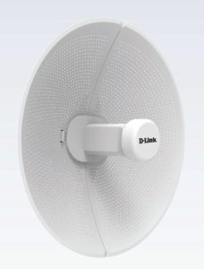

Before You Begin
This installation guide provides basic instructions for installing the DAP-3712 on your network. The device should be ensured that systems employing high gain directional antennas are used exclusively for fixed, point-to-point operations. For additional information about how to use the access point, please see the User Manual from the D-Link support website.
Package Contents
This DAP-3712 should include the following items:
- 20 km Long Range 802.11ac Wireless Bridge
- PoE injector
- Power cord
- Mounting tie
- Quick Start Guide
If any of the above items are damaged or missing, please contact your local D-Link reseller
Note: Using a power supply with a different voltage than the one recommended for the device will cause damage and void the warranty for this product.
System Requirements
- Microsoft Windows®, or a Linux-based operating system
- Ethernet port
- Microsoft Edge, Firefox 60.0, or Chrome 68.0.3440.106
Hardware Overview
LED Indicators
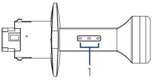
Figure 1: DAP-3712 LEDs

| # | LED | Description |
| 1 | Signal Strengt | Signal strength indicators. One light indicates a weak signal. Two lights indicate a medium signal. Three lights indicate a strong signal. |
Table 1: LED Descriptions
Interface Connectors

Figure 2: DAP-3712 Interface
| # | Feature | Description |
| 1 | PoE Por | Uses a standard Ethernet cable to connect the device to a PoE power source such as a PoE switch or PoE injector. |
| 2 | Reset Button | Resets the device to its factory settings |
Table 2: Interface Descriptions
Installation
Assembling the Access Point
- Assemble the dish of the DAP-3712 by sliding the two halves together until they lock in place.
- Connect the antenna and base through the hole in the center of the dish.
- Thread a standard RJ-45 Ethernet cable through the cover for the PoE port on the underside of the DAP-3712. Insert the cable into the PoE port, then attach the cover to the device.
- Connect the adjustment kit to the base of the DAP-3712 by pressing it in until it clicks and locks in place. Use the adjustment kit to position the antenna at the desired angle.


Preparation before Installation
Before installing the DAP-3712, check the distance between the two sides and ensure that they are within wireless signal range of each other. It may be helpful to use a Graphic Information System (GIS) program such as Google Earth to check for obstructions between the two sites. If there is an obstruction, it may help to install the DAP-3712 as high as possible to prevent the signal from being blocked.
Figure 7: Positioning the DAP-3712 with a GIS

Note: Ensure that both devices have the same model number and are running the same firmware version. The radiation pattern and wireless protocol of the DAP-3712 is designed for high-performance bridge connectivity. Using different models or models with mismatched firmware versions may cause problems, such as performance degradation or a reduction in coverage area.
Powering the Access Point
To power the DAP-3712, use a standard Ethernet cable to connect the PoE port on the DAP-3712 to a 48 V PoE injector.
Cable Requirements
Use a CAT 5 cable with an even sheath. The Ethernet ports on the DAP-3712 access point cannot accept a CAT 5 cable that has an uneven sheath; the RJ-45 connector on the cable will not fit properly into the receptacle on the access point.
Configuring the First DAP-3712 in Access Point Mode
- Use an Ethernet cable to connect the LAN port on the DAP-3712 to the PoE Out port on the PoE injector. Using another cable, attach the PoE injector to your switch or management computer.
- Ensure the computer is configured with the static IP address 192.168.0.2 and a subnet mask of 255.255.255.0.
- Launch a web browser. Enter 192.168.0.50 in the address field of your browser.
- Log in to the administration user interface.
The default login information is:
Username: admin
Password: admin - Follow the Setup Wizard’s instructions to configure the device in Access PointMode. Refer to Figure 9: Using the Setup Wizard for details.


Configuring the Second DAP-3712 in Client Mode
- Follow steps 1-4 of the instructions above to power on the device. Launch the Setup Wizard to configure the device in Client Mode.
- T o avoid an IP address conflict, change the IPv4 address so that it is different from the first DAP-3712’s IP address (for instance, by changing it to 192.168.0.51, as in the following screenshot).
- On step four of the Setup Wizard (Wireless), select Client from the dropdown list. Enter the same SSID and key that you entered when configuring the first device.
- To confirm that wireless connectivity between the two devices is configured correctly, navigate to the Status page and check the information under Associated Stations (shown below).


Mounting the Device
Installation Recommendations
If you plan to install the DAP-3712 on a pole, orient the front of the access point toward the intended coverage area. The radio antenna transmits through the front of the access point but not through the reverse side (where the bracket is).
Be sure to install the device at a height that ensures that the alignment between the devices is visible and there is no obstruction in the middle.
Checking the Signal Strength
Before fixing the device in place, slowly pan the DAP-3712 from side to side and check the LED indicator to find the position where the signal is strongest.
Mounting on a Pole
- Hold the DAP-3712 against the pole in the desired position.
- Thread the metal mounting tie through the hole on the base of the DAP-3712 and and wrap it around the pole. Fasten the tie to secure the device against the pole.


Once completed, your network will resemble the following diagram.

RF Frequency Requirements
This device is for outdoor use only. High power radars are allocated as primary users of the 5150 – 5250 MHz and 5725 – 5850 MHz bands. These radar stations can cause interference with or damage the PoE adapter of this device. This is a fixed point-to-point device.
Appendix – Statements
FCC Statement
This equipment has been tested and found to comply with the limits for a Class A digital device, pursuant to Part 15 of the FCC Rules. These limits are designed to provide reasonable protection against harmful interference when the equipment is operated in a commercial environment. This equipment generates, uses, and can radiate radio frequency energy and, if not installed and used in accordance with the instruction manual, may cause harmful interference to radio communications. Operation of this equipment in a residential area is likely to cause harmful interference in which case the user will be required to correct the interference at his own expense.
FCC Radiation Exposure Statement
This device complies with FCC radiation exposure limits set forth for an uncontrolled environment and it also complies with Part 15 of the FCC RF Rules. This equipment must be installed and operated in accordance with provided instructions and the antenna(s) used for this transmitter must be installed to provide a separation distance of at least 20 cm from all persons and must not be co-located or operating in conjunction with any other antenna or transmitter. End-users and installers must be provided with antenna installation instructions and consider removing the no collocation statement.
This device complies with Part 15 of the FCC Rules. Operation is subject to the following two conditions:
(1) this device may not cause harmful interference, and
(2) this device must accept any interference received, including interference that may cause undesired operation.
Caution!
Any changes or modifications not expressly approved by the party responsible for compliance could void the user’s authority to operate the equipment.