D-Link DWL-8720AP Unified AC Dual-band Outdoor
PoE Access Point Installation Guide
D-Link DWL-8720AP Unified AC Dual-band Outdoor PoE Access Point Installation Guide

Before You Begin
This installation guide provides instructions for installing the DWL-8720AP on your network. Additional documentation is also available on the D-Link support website.
Package Contents
This DWL-8720AP package includes the following items:
- DWL-8720AP Access Point
- Mounting Plate and Hardware (U-bolts and nut fasteners, screws and washers)
- Grounding Wire
- Console Cable
- Quick Start Guide
If any of the above items are damaged or missing, please contact your local D-Link reseller.
Note: To power the unit, use an 802.3af or 802.3at PoE wwitch or PoE injector. This product is intended to be supplied by a LPS (Limited Power Source) marked UL Listed Power Unit, and its output is rated at 48 V DC (PoE), 0.6 A min., and has a TMA of 60 o C.
System Requirements
- Computers with Windows®, Macintosh®, or Linux-based operating systems with an installed Ethernet Adapter.
- Internet Explorer 11, Safari 7, Firefox 28, or Google Chrome 33 and above (for configuration).
Hardware Overview
LED Indicators

Note: For the LED positions, please unscrew the protective cap to line up the device with the diagram above.

Table 1: LED Description
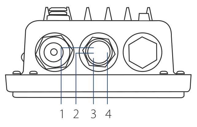
Interface Connectors

Figure 2: Bottom Connectors

Table 2: Interface Description

Figure 3: Rear Connectors

Table 3: Interface Description
Installation
Using Power over Ethernet (PoE)
1. Use a standard Ethernet cable to connect the LAN1 (PoE) port on the DWL-8720AP to a PoE power source device such as an 802.3af or 802.3at PoE switch or PoE injector.
Note: If you require a PoE injector such as D-Link’s DPE-311GI, please contact your reseller to order it.
Configuration
Manual Configuration
Note: D-Link recommends manually configuring the device before mounting it. The management computer, DHCP server and DWL-8720AP must be in the same subnet.
Use the following method to access the web user interface:
Connecting through Ethernet
- Use an Ethernet cable to connect the DWL-8720AP to the management computer, or to the switch or router the
management computer is connected to. - Open a web browser and enter the IP address 10.90.90.91 and press Enter
- Log in to the administration user interface. The default login information is
Username: admin
Password: admin - You can now assign a static IP address, or you can use a DHCP server on your network to assign network information to the DWL-8720AP. The DHCP client on the DWL-8720AP is enabled by default.
Mounting

Figure 4: LAN Port Waterproof Enclosure
1. Connect an Ethernet Cable to the LAN (PoE) port on the DWL-8720AP. Use the LAN port waterproof enclosures to seal the ports.
Pole Mounting

Figure 5: Attaching the Mounting Base
1. Secure the mount base to the pole using the U-bolt and the four included nut fasteners.

Figure 6: Mounting the Device
2. Align and attach the DWL-8720AP to the mounting base using the four included screws and washers.
Wall Mounting

Figure 7: Attaching the Mounting Plate
1. Align and attach the DWL-8720AP to the mounting plate using the four included screws and washers.

Figure 8: Mounting the Device
2. Use the mounting plate to mark where to drill the holes in the wall.
3. Drill holes on the markings and place the included anchors into the drilled holes.
4. Align and place the mounting plate on top of the anchors and use the included screws to secure the DWL-8720AP to the wall.
Connecting the Grounding Wire

Figure 9: Attaching the Grounding Wire
1. A grounding wire is recommended to protect your device from lightning strikes and the buildup of static electricity. Attach the grounding wire to the DWL-8720AP using the included screw.

Figure 10: Attaching the Grounding Wire
2. Tighten the grounding wire to the DWL-8720AP until it is securely attached.

Figure 11: Attaching the Grounding Wire
3. Attach the other end of the grounding wire to either the wall or the pole mount. Ensure that the wall or the pole mount is connected to an electrical ground.
TECHNICAL SUPPORT: dlink.com/support
Appendix – Statements
Federal Communication Commission Interference Statement
This equipment has been tested and found to comply with the limits for a Class B digital device, pursuant to Part 15 of the FCC Rules. These limits are designed to provide reasonable protection against harmful interference in a residential installation. This equipment generates, uses and can radiate radio frequency energy and, if not installed and used in accordance with the instructions, may cause harmful interference to radio communications. However, there is no guarantee that interference will not occur in a particular installation. If this equipment does cause harmful interference to radio or television reception, which can be determined by turning the equipment off and on, the user is encouraged to try to correct the interference by one of the following measures:
- Reorient or relocate the receiving antenna.
- Increase the separation between the equipment and receiver.
- Connect the equipment into an outlet on a circuit different from that to which the receiver is connected.
- Consult the dealer or an experienced radio/TV technician for help.
FCC Caution: Any changes or modifications not expressly approved by the party responsible for compliance could void the user’s authority to operate this equipment.
This device complies with Part 15 of the FCC Rules. Operation is subject to the following two conditions: (1) This device may not cause harmful interference, and (2) this device must accept any interference received, including interference that may cause undesired operation.
- This device meets all the other requirements specified in Part 15E, Section 15.407 of the FCC Rules.
IMPORTANT NOTE:
Radiation Exposure Statement:
This equipment complies with FCC radiation exposure limits set forth for an uncontrolled environment. This equipment should be installed and operated with minimum distance 23.2 cm between the radiator & your body
This transmitter must not be co-located or operating in conjunction with any other antenna or transmitter.
Country Code selection feature to be disabled for products marketed to the US/CANADA
Professional installation instruction
Please be advised that due to the unique function supplied by this product, the device is intended for use with our interactive entertainment software and licensed third-party only. The product will be distributed through controlled distribution channel and installed by trained professional and will not be sold directly to the general public through retail store.
- Installation personal
This product is designed for specific application and needs to be installed by a qualified personal who has RF and related rule knowledge. The general user shall not attempt to install or change the setting. - Installation location
The product shall be installed at a location where the radiating antenna can be kept 23.2 cm from nearby person in normal operation condition to meet regulatory RF exposure requirement. - External antenna
Use only the antennas which have been approved by the applicant. The non-approved antenna(s) may produce unwanted spurious or excessive RF transmitting power which may lead to the violation of FCC limit and is prohibited. - Installation procedure
Please refer to user’s manual for the detail. - Note to the installer:
To comply with the FCC U-NII Band 1 above 30-degree EIRP emission limit (21 dBm), installer must ensure that the final installation will not emit more than 21 dBm EIRP power 30-degrees above the horizon based on the antenna radiation pattern of the device.
This device complies with Industry Canada’s licence-exempt RSSs. Operation is subject to the following two conditions:
(1) This device may not cause interference; and (2) This device must accept any interference, including interference that may cause undesired operation of the device.
(i) the device for operation in the band 5150-5250 MHz is only for indoor use to reduce the potential for harmful interference to co-channel mobile satellite systems;
(ii) for devices with detachable antenna(s), the maximum antenna gain permitted for devices in the bands 5250-5350 MHz and 5470-5725 MHz shall be such that the equipment still complies with the e.i.r.p. limit; (detachable antenna only)
(iii) for devices with detachable antenna(s), the maximum antenna gain permitted for devices in the band 5725-5850 MHz shall be such that the equipment still complies with the e.i.r.p. limits as appropriate; (detachable antenna only)
(iv) where applicable, antenna type(s), antenna models(s), and worst-case tilt angle(s) necessary to remain compliant with the e.i.r.p. elevation mask requirement set forth in section 6.2.2.3 shall be clearly indicated.
DETACHABLE ANTENNA USAGE
This radio transmitter (IC: 4216A-WL8720APA1 / DWL-8720APA1) has been approved by ISED to operate with the antenna type listed below with maximum permissible gain indicated. Antenna types not included in this list, having a gain greater than the maximum gain indicated for that type, are strictly prohibited for use with this device.
Approved antenna(s) list

Radiation Exposure Statement:
This equipment complies with IC radiation exposure limits set forth for an uncontrolled environment.
This equipment should be installed and operated with minimum distance 26.6cm between the radiator & your body.
Professional installation instruction
- Installation personal
This product is designed for specific application and needs to be installed by a qualified personal who has RF and related rule knowledge. The general user shall not attempt to install or change the setting. - Installation location
The product shall be installed at a location where the radiating antenna can be kept 26.6cm from nearby person in normal operation condition to meet regulatory RF exposure requirement. - External antenna
Use only the antennas which have been approved by the applicant. The non-approved antenna(s) may produce unwanted spurious or excessive RF transmitting power which may lead to the violation of ISED limit and is prohibited. - Installation procedure
Please refer to user’s manual for the detail. - Warning
Please carefully select the installation position and make sure that the final output power does not exceed the limit set force in relevant rules. The violation of the rule could lead to serious federal penalty
CE Mark Warning:
This is a Class B product. In a domestic environment, this product may cause radio interference, in which case the user may be required to take adequate measures.
1. A safety grounding system is necessary to protect your outdoor installation from lightning strikes and the build-up of static electricity.
When mounting the Outdoor Access Point on the pole or solid wall, you have to connect the Outdoor Access Point to the same grounding system* with the AC wall outlet.
* The grounding system must comply with the National Electrical Code and safety standards that applyin your country
2. Instructions for the installation of that conductor to building earth by a SKILLED PERSON.
3. Please contact the authorized distributor of D-Link for related accessories (outdoor interconnection cable, cable gland, cable, etc.) for purchase and installation.


Ver. 1.00(WW)_130x183
2020/07/29