D-Link DNR-4020-16P Connect 16-Channel H.265 PoE Network Video Recorder Installation Guide

JustConnect 16-Channel H.265 PoE Network Video Recorder
DNR-4020-16P


Before You Begin
This Quick Installation Guide gives you step-by-step instructions for setting up your DNR-4020-16P JustConnect 16-Channel H.265 PoE Network Video Recorder. The model you have purchased may appear slightly different from the one shown in the illustrations. For more detailed information about the NVR, please refer to the User Manual.
Package Contents
This DNR-4020-16P package should include the following items:
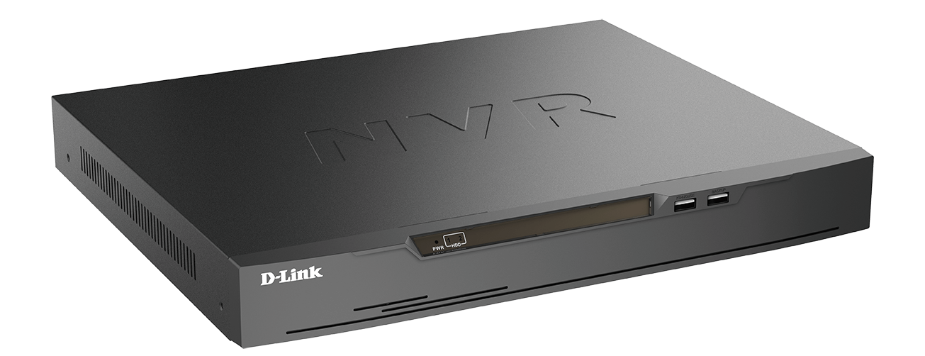
- DNR-4020-16P JustConnect 16-Channel H.265 PoE Network Video Recorder
- Power cord
- 8 x hard disk screw
- 2 x rack mount bracket
- 6 x rack mount bracket screw
- 2 x terminal block
- Documentation
If any of the above items are damaged or missing, please contact your local D-Link reseller.
System Requirements
- Microsoft Windows®
- Microsoft Edge, Internet Explorer, Firefox, Chrome, or Safari
Hardware Overview
Front Panel LED Indicators

| # | LED | Description |
| 1 | Power Indicator | Lights up when the device is receiving power and the power switch is turned on. |
| 2 | HDD Indicator | Hard disk status indicator. This indicator flashes when data is being transmitted. |
Table 1: Front Panel LED Indicator Descriptions
Front Panel Interface Connectors

| # | Interface | Description |
| 1 | KB/Mouse Port | USB port for a keyboard or mouse. |
| 2 | Backup Port | USB port for a flash drive. |
Table 2: Front Panel Interface Connector Descriptions
Rear Panel Interface Connectors

| # | Feature | Description |
| 1 | PoE Ports | PoE ports that offer a direct connection to up to 16 cameras. |
| 2 | LAN | Uses a standard Ethernet cable to connect to a switch or router. |
| 3 | Audio OUT | Connect external speakers for live audio or audio playback. |
| 4 | VGA Output | The output connector for a VGA monitor. |
| 5 | USB 2.0 Port | Connect a USB storage device such as a flash drive. |
| 6 | Power | Connect the supplied power cord to the input port. |
| 7 | Audio IN | Connect a microphone to use 2-way communication with your camera(s). |
| 8 | HDMI Output | The output connector for an HDMI monitor. |
| 9 | Alarm I/O | Alarm I/O ports for connecting to sensors or other devices. |
| 10 | Power Switch | Press “1” to turn the device on, .,0..to turn it off. |
Table 3: Rear Panel Interface Connector Descriptions
Hardware Installation
Before You Begin
Observe the following precautions to help prevent shutdowns, equipment failures, and personal injury:
- Install the DNR-4020-16P in a cool and dry place.
- Install the DNR-4020-16P in a site free from strong electromagnetic sources, vibration, dust, excessive moisture, and direct sunlight.
- Visually inspect the power connector and make sure that it is fully secure.
- Do not stack any devices on top of the DNR-4020-16P.
Hard Drive Installation
Note: The hard drive of the device is not included and must be provided by the user.
- Remove the fixing screws from the top cover of the DNR-4020-16P, then remove the top cover from the device.
- Insert two screws into the holes near the rear panel of the hard drive. Turn the screws twice, so that they protrude slightly.
- Insert the hard drive into the drive bay of the DNR-4020-16P, fitting the heads of the two screws into the slots indicated in Figure 6: Inserting the Hard Drive. Slide the hard drive toward the center of the DNR-4020-16P so that it locks into position.
- Turn the device over and secure the hard drive inside the device by screwing the provided screws into the four remaining holes on the bottom of the DNR-4020-16P.
- If desired, install a second hard drive by repeating steps 1-4. Attach the hard disk data cable and power cable to the device, then reattach the top cover and fasten the fixing screws.


Management Options
VGA or HDMI Connection
- Connect your network cameras directly by using the PoE ports on the back of the device, or connect them to a switch or router that is connected to the DNR-4020-16P.
- Connect the power cord to the port on the rear panel of the DNR-4020-16P and turn the power switch on.
- Connect a VGA or HDMI display to the corresponding port on the back of the device. To control the GUI, connect a USB mouse to the USB port on the front panel.
- The Activation window will appear in the center of the screen. Select your preferred language, and enter a password that will be used to access the management interface. Confirm the password by retyping it.
- In the Default channel password field, enter the password that will be used to view and configure the device’s channels. Click OK to continue.
- On the next screen, reenter the admin password and click Login to access the management interface.
Mobile Interface
Once the DNR-4020-16P has been activated, it can also be managed using the JustConnect+ mobile app.
- Download the JustConnect+ app from theApp Store or Google Play by scanning the following QR code.
https://d1rvtd08ngd4ef.cloudfront.net/new+mydlink/getUAP03.html?ios=599879455&aos=com.vuexpro - Open the JustConnect+ app and follow the onscreen instructions to discover and connect to NVRs on the same network as your mobile device. Alternately, enter the domain name or IP address of your DNR-4020-16P to connect to it remotely.
By default, the DNR-4020-16P will receive its IP address via DHCP. It will default to 192.168.0.20 if it is unable to receive an IP address from a DHCP server.

Web User Interface
The DNR-4020-16P can also be controlled using a web browser.
- Open a web browser and enter the IP address of the device in the address field.
- Log in to the web user interface using the same information used to access the management interface.
Additional Information
If you are encountering problems setting up your device, please refer to the user manual.
Additional help is available online. To find out more about D-Link products or marketing information, please visit the D-Link support website at http://dlink.com/support/.
Warranty Information
The D-Link Limited Lifetime Warranty information is available at the following website: http://warranty.dlink.com/.
Appendix – Statements
Regulatory Statements (Only for Class A product)
Federal Communication Commission Interference Statement
This equipment has been tested and found to comply with the limits for a Class A digital device, pursuant to part 15 of the FCC Rules. These limits are designed to provide reasonable protection against harmful interference when the equipment is operated in a commercial environment. This equipment generates, uses, and can radiate radio frequency energy and, if not installed and used in accordance with the instruction manual, may cause harmful interference to radio communications. Operation of this equipment in a residential area is likely to cause harmful interference in which case the user will be required to correct the interference at his own expense.
Non-modification Statement
Any changes or modifications not expressly approved by the party responsible for compliance could void the user’s authority to operate the equipment.
Caution
This device complies with Part 15 of the FCC Rules. Operation is subject to the following two conditions:
(1) This device may not cause harmful interference, and (2) this device must accept any interference received, including interference that may cause undesired operation. Innovation, Science and Economic Development Canada (ISED) Statement:
This Class A digital apparatus complies with Canadian ICES-003.
CE EMI CLASS A WARNING
This equipment is compliant with Class A of CISPR 32. In a residential environment, this equipment may cause radio interference.
CE EMI Class A Warning
This equipment is compliant with Class A of CISPR 32. In a residential environment, this equipment may cause radio interference.
SAFETY INSTRUCTIONS
The following general safety guidelines are provided to help ensure your own personal safety and protect your product from potential damage. Remember to consult the product user instructions for more details.
- Static electricity can be harmful to electronic components. Discharge static electricity from your body (i.e. touching grounded bare metal) before touching the product.
- Do not attempt to service the product and never disassemble the product. For some products with a user-replaceable battery, please read and follow the instructions in the user manual.
- Do not spill food or liquid on your product and never push any objects into the openings of your product.
- Do not use this product near water, areas with high humidity, or condensation unless the product is specifically rated for outdoor application.
- Keep the product away from radiators and other heat sources.
- Always unplug the product from mains power before cleaning and use a dry lint-free cloth only.
DISPOSING AND RECYCLING YOUR PRODUCT


GPL Code Statement
This D-Link product includes software code developed by third parties, including software code subject to the GNU General Public License (“GPL”) or GNU Lesser General Public License (“LGPL”). As applicable, the terms of the GPL and LGPL, and information on obtaining access to the GPL code and LGPL code used in this product, are available to view the full GPL Code Statement at: https://tsd.dlink.com.tw/GPL
The GPL code and LGPL Code used in this product is distributed WITHOUT ANY WARRANTY and is subject to the copyrights of one or more authors. For details, see the GPL code and the LGPL code for this product and the terms of the GPL and LGPL.
Written Offer for GPL and LGPL Source Code
Where such specific license terms entitle you to the source code of such software, D-Link will provide upon written request via email and/or traditional paper mail the applicable GPL and LGPL source code files via CDROM for a nominal cost to cover shipping and media charges as allowed under the GPL and LGPL.
Please direct all inquiries to:
Email:
Snail Mail: Attn: GPLSOURCE REQUEST
D-Link Systems, Inc.
17595 Mt. Herrmann Street
Fountain Valley, CA 92708
Notes

Ver. 1.00(WW)_90x130
2020/09/28
101-010-0199-01