D-Link DWM-315 4G LTE M2M Router Installation Guide


Quick Installation Guide
4G LTE M2M Router
DWM-315

Additional documentation is also available on the D-Link website
Before You Begin
This Quick Installation Guide gives you step-by-step instructions for setting up your DWM-315 4G LTE M2M Router. The model you have purchased may appear slightly different from the one shown in the illustrations. For more detailed information about the router, please refer to the User Manual.
Package Contents
This DWM-315 package should include the following items:
- DWM-315 4G LTE M2M Router
- C adapter with 5.5 mm DC connector
- RJ-45 cable
- 2 x external LTE antennas
- External GPS antenna (optional)
- Quick Installation Guide
- Warranty Card
If any of the above items are damaged or missing, please contact your local D-Link reseller.
Note: Using a power supply with a different voltage than the one recommended for the device will cause damage and void the warranty for this product.
System Requirements
- Microsoft Windows®, or a Linux-based operating system
- An available Ethernet port
- Microsoft Edge, Firefox 60.0, or Chrome 68.0.3440.106
Hardware Overview
Top Panel LED Indicators

Figure 1: Top Panel LED Indicators
| # | LED | Description | |
| 1 | Internet | A green light indicates that a WAN | |
| 2 | Signal Strength |
Green | Signal strength is at 51100%. |
| Orange | Signal strength is at 25-50%. | ||
| Red | Signal strength is <25%. | ||
| Flashing Red | No signal. | ||
Table 1: Top Panel LED Descriptions
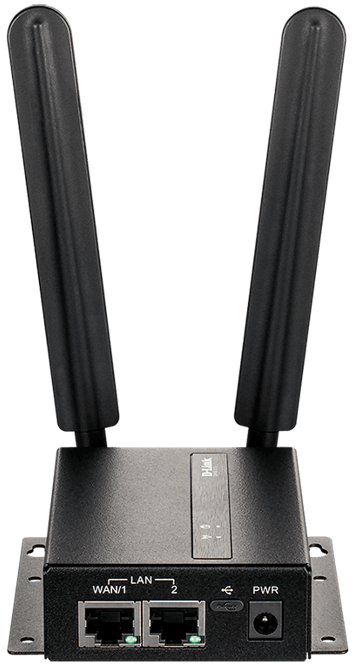
Front Panel Interface Connectors

# |
Interface | Description |
| 1 | WAN/
LAN Port |
10/100/1000 Mbps Ethernet WAN/LAN port. |
| 2 | Ethernet
LAN Port |
10/100/1000 Mbps Ethernet LAN port. |
| 3 | USB Port | MicroUSB 2.0 port. |
| 4 | Power Input | Input for the power adapter. |
Table 2: Front Panel Interface Connector Descriptions
Rear Panel Interface Connectors

Figure 3: Rear Panel Interface Connectors
# |
Feature | Description |
| 1 | Security Plate |
Security plate covering the SIM and microSD card slots. |
| 2 | MicroSD
|
Slot for a microSD card for storage. |
| 3 | SIM A |
Primary SIM card. |
| 4 | Reset |
Press and hold for 3 seconds to reset the device. |
| 5 | SIM B |
Secondary BcTaHoBiTb micro-SIM-KapTy B cno card. |
| 6 | SMA Connector
|
Female SMA connector for the main antenna. |
SMA Connector
|
Female SMA connector for the GPS antenna. | |
| 8 | SMA Connector
|
Female SMA connector for the auxiliary antenna. |
Table 3: Rear Panel Interface
Connector Descriptions
Hardware Installation
Before You Begin
Observe the following precautions to help prevent shutdowns, equipment failures, and personal injury:
- Install the DWM-315 in a cool and dry place.
- Install the DWM-315 in a site free from strong electromagnetic sources, vibration, dust, excessive moisture, and direct sunlight.
- Place antennas in an unobstructed area with a clear mobile signal. Avoid metal boxes, brick walls, and other dense materials.
- Visually inspect the power connector and make sure that it is fully secure.
- Do not stack any devices on top of the DWM-315.
Installing SIM Card(s)
The DWM-315 is equipped with dual-SIM slots.
At least one active SIM card with Internet access is required for proper operation.
- Unscrew the two screws on the security plate to remove it and get access to the SIM card slots.
- Insert a micro-SIM card into the slot labeled SIM A with the contacts facing down. If you wish to install a second SIM card, insert it into the slot labeled SIM B.
- Gently press the micro-SIM into the slot until it locks into place. To remove it, press again and the SIM card will be ejected.
- Screw the security plate back on using the two screws removed earlier in order to protect the SIM card slots.

Note: SIM behavior must be configured from the web UI before an Internet connection can be established.
Attach the External Antennas
The DWM-315 requires two external antennas to function correctly. The included antennas are interchangeable, but third-party antennas may require connection to specific ports.

- Attach the two LTE antennas to the SMA connectors on the back of the router labeled “Main” and “AUX.” Turn clockwise to fasten the antenna.
- Place antennas where they will receive an optimal signal. Arrange them so they point upward.
Powering the Device
The DWM-315 features flexible power input ranging from 5 volts / 2 amps to 18 volts /0.7 amps. A minimum of 10 watts total is recommended.
Using the Included AC Adapter
- Attach the barrel connector of the included AC adapter to the power port on the front panel.
- Attach the AC adapter to an appropriate AC socket.
Connecting Devices
After the DWM-315 has been successfully installed, the router can be connected to the end device and the Internet via the LAN and WAN port.
- To connect to the Internet, insert one end of a standard Cat 5/5e/6 RJ-45 Ethernet cable into the WAN port on your device, and insert the other end into the corresponding port on your modem.
- Use a standard Category 5/5e/6 RJ-45 Ethernet cable to connect the end device to the router. The port will auto-negotiate to the highest possible port speed based on the connected device. Note that the DWM-315 supports a maximum transfer speed of 300 Mbps over Ethernet.
Management Options
Before You Begin
The D-Link router can be managed by using the Web User Interface (Web UI), Telnet, or Simple Network Management Protocol (SNMP) management interfaces. If you wish to manage a single D-Link router, the Web UI may be the best option. Each router must be assigned its own IP address, which is used for communication with the management PC. Please refer to the following installation instructions to get started with the Web UI and SNMP management interfaces.
Web User Interface
Once the router has been successfully installed, you can begin configuration, monitor the LED panel, and display graphical statistics using a web browser. Supported browsers include Microsoft® Internet Explorer, Firefox, Chrome, and Safari.
You need the following equipment to access the Web UI of your device:
- A PC with an RJ-45 Ethernet port
- A standard Ethernet cable
- Connect the Ethernet cable to the router’s Ethernet port and to the Ethernet port on the PC.
- Configure the PC’s IP address to be in the network segment as the router. The router’s default IP address is 192.168.0.1, with subnet mask 255.255.255.0. For example, to connect to the router using the default settings, your PC should have an IP address in the range 192.168.0.2.254 and a subnet mask of 255.255.255.0.
- Open a web browser and enter http://192.168.0.1/ in the address field.
- Log in to the administrator user interface.
The default login information is:
Username: admin
Password: admin.
SNMP
You can manage the device with any SNMP-compatible program. The SNMP function is disabled by default and must be enabled on the device first by using the Web UI, as described in the previous section.
Additional Information
If you are encountering problems setting up your network, please refer to the user manual.
Additional help is available online. To find out more about D-Link products, marketing information, or to view or download the user manual, please visit the D-Link support website at http://dlink.com/support/.
Warranty Information
The D-Link Limited Lifetime Warranty information is available at the following website: http://warranty.dlink.com/.
TECHNICAL SUPPORT

2020/07/30
11500Y200Y003Z1A1
