D-Link DGS-3620-52P 52 Port xStack L3 Managed Stackable Gigabit Switch Installation Guide


D-Link
DGS-3620-52P
48 10/100/1000Base-T PoE+ ports + 4 10GE SFP+ ports L3 Stackable Managed Switch

Quick Installation Guide
Introduction
This Quick Installation Guide gives instructions for setting up the D-Link DGS-3620-52P switch. The model you have purchased may appear slightly different from those shown in the illustrations. For more detailed information about the device, its components, making network connections, and technical specifications, please refer to the D-Link website http://www.dlink.com/
Package Contents
Open the shipping carton of the Switch and carefully unpack its contents. The carton should contain the following items:
- One DGS-3620-52P switch
- One AC power cord
- One console cable (RJ-45 to RS-232)
- Two rack mounting brackets
- Mounting kit
- Four rubber feet with adhesive backing
- One Quick Installation Guide
If any of the above items are damaged or missing, please contact your local reseller for replacement.
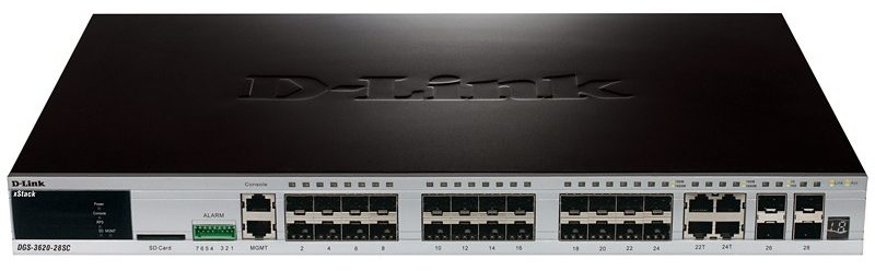
Hardware Overview
LED Indicators |

| LED Indicative | Colour | Status | Description |
| Power | Green | Solid Green | Power on. |
| Light off | Power off. | ||
| Console | Green | Blinking Green | During the Power-On Self Test (POST). |
| Light off | When the POST is finished. | ||
| Solid Green | When a user is logged in through the console port. | ||
| RPS | Green | Solid Green | A redundant Power Supply is in use. |
| Light off | RPS is not in use. | ||
| Blinking Green | RPS is connected. | ||
| SD | Green / Red | Solid Green | If a Secure Digital (SD) card is plugged in. |
| Blinking Green | The Switch is reading or writing data to and from the SD card. | ||
| Light off | No SD card is plugged into the SD port. | ||
| Solid Red | An SD card failure has been detected. | ||
| Stack ID | 1 — 12 |
The box ID is assigned either by the user (static mode) or by the system (automatic mode). For standalone Switches, this will display the number “1”. | |
H |
The device was assigned as the stacking Master. | ||
h |
The device was selected to be the Backup Master. | ||
G |
The Safeguard Engine feature enters the exhausted mode. | ||
| Link/Act | Green / Orange |
Solid Green | When there is a secure connection to a 1000Mbps Ethernet device at any of the ports. |
| Solid Orange | When there is a secure connection to a 10/100Mbps Ethernet device at any of the ports. | ||
| Blinking Green | When a 1000Mbps port is active. | ||
| Blinking Orange | When a 10/100Mbps port is active. | ||
| Light off | No link or activity. | ||
| PoE | Green / Orange |
Solid Green | The corresponding ports are feeding power to the PoE devices plugged in. |
| Solid Orange | The port is in an error condition state. | ||
| Light off | The ports are not supplying power to the devices plugged into the ports. | ||
| MGMT | Green | Solid Green | Console on. |
| Blinking Green | Secure connection established. | ||
| Light off | Console off. | ||
Installation Guidelines
Desktop or Shelf Installation
When installing the switch on a desktop or shelf, the rubber feet included with the device must be attached on the bottom at each corner of the device’s base. Allow enough
ventilation space between the device and the objects around it.

Installing the Switch in a Standard 19” Rack
The Switch can be mounted in a standard 19″(1U) rack using the provided mounting brackets. Fasten the mounting brackets to the sides of the Switch using the screws
provided.

Fasten the mounting brackets in any available open space in the rack using the screws provided.

Installing Transceivers into the Transceiver Ports
The Switch is equipped with Small Form-factor Pluggable (SFP) and SFP+ ports, which supply connecting SFP, WDM SFP, and SFP+ transceivers.

Connecting to Power
Power On (AC Power)
Plug one end of the AC power cord into the power socket of the Switch and the other end into the local power source outlet.
Power Failure (AC Power)
In the event of a power failure, just as a precaution, unplug the power cord from the Switch. After the power returns, plug the power cord back into the power socket of the
Switch.
Connecting to a Redundant Power Supply
The DPS-700 is connected to the Master Switch using a 22-pin DC power cable. A standard, three-pronged AC power cable connects the redundant power supply to the main
power source.

- Disconnect the Switch from the main AC power source.
- Insert one end of the 22-pin DC power cable into the port on the switch and the other end into the RPS.
- Using a standard AC power cord, connect the RPS to the main AC power source. A green LED on the front panel of the RPS will illuminate to indicate a successful connection.
- Reconnect the AC power cord to the AC power port of the Switch. The RPS LED indicator on the front panel of the Switch will indicate that an RPS is present and now in
operation.
No configuration is needed in the Switch software for this installation.

Switch Connections
Switch to End Node
End node is a generic name for edge networking devices that will be connected to this switch. Typical examples of end nodes are Personal Computers (PCs), Notebooks, Access Points, Print Servers, VoIP Phones, and more. An end node connects to the Switch via a twisted-pair UTP/STP cable. Connect the end node to any of the 1000Base-T ports of the Switch. The Link/Act LEDs for each Ethernet port turn green or orange when the link is active. A blinking LED indicates packet activity on that port.


Switch to Switch
There is a great deal of flexibility on how connections are made using the appropriate cabling.
- Connect a 10Base-T switch port to the Switch via a twisted-pair Category 3, 4, or 5 UTP/STP cable.
- Connect a 100Base-TX switch port to the Switch via a twisted-pair Category 5 UTP/STP cable.
- Connect 1000Base-T switch port to the Switch via a twisted-pair Category 5e UTP/STP cable.
- Connect switch supporting a fiber-optic uplink to the Switch’s SFP ports via fiber-optic cabling.

Connect to a Network Backbone or Server
The 1000Base-T SFP ports are ideal for uplinking to a network backbone, server or server farm.

Management Options
Web-based Management Interface
After successfully installing the Switch, the user can configure the Switch, monitor the LED panel, and display statistics graphically using a web browser, such as Firefox (version 3.0 and higher) or Microsoft® Internet Explorer (version 5.0 and higher).
SNMP-based Management
The Switch can be managed with an SNMP-compatible console program. The Switch supports SNMP version 1.0, version 2.0, and version 3.0.
Command Line Interface (CLI)
The user can also connect a computer to the serial console port to access the Switch. The command-line interface provides complete access to all Switch management features.
Alternatively, the Switch can also be managed, in-band, by using a Telnet connection.
Connecting the Console Port
To use the console port, the following equipment is needed:
- A terminal or a computer with both an RS-232 serial port the ability to emulate a terminal.
- A console cable with a male DB-9 connector on one end and an RJ-45 connection on the other. This cable should be included with the Switch.
To configure the terminal emulation software as follows:
- Select the appropriate serial port (COM port 1 or COM port 2).
- Set the data rate to 115200 baud.
- Set the data format to 8 data bits, 1 stop bit, and no parity.
- Set flow control to none.
Then, under Properties, select VT100 for Emulation mode. Select Terminal keys for Function, Arrow, and Ctrl keys. Make sure to use Terminal keys (not Windows keys) are selected. After you have correctly set up the terminal, plug the power cord into the power receptacle on the back of the Switch. The boot sequence appears in the terminal. After the boot sequence completes, the console login screen displays.
Connecting to the Switch for the First Time
Upon initial connection to the Switch, the login screen appears (see example below).
D G S – 3 6 2 0 – 5 2 P G i g a b i t E t h e r n e t S w i t c h
Command Line Interface
Firmware: Build 2.60.016
Copyright(C) 2013 D-Link Corporation. All rights reserved.
UserName:
Press Enter in both the Username and Password fields. Then access will be given to enter commands after the command prompt: DGS-3620-52P: admin#
There is no initial username or password. Leave the Username and Password fields blank.

Connecting to the Management Port
The front panel of the Switch features a Management port that can be used to connect to a computer using a standard Ethernet cable. A web browser or Telnet client can be used to connect to the Switch using the MGMT port.
The default IP address of the Management port is 192.168.0.1, and a subnet mask of 255.255.255.0. Make sure that the computer being used for Switch management has a
the non-conflicting IP address in the 192.168.0.x subnet.
The IP settings or enabled status of the Management port can be changed through the console port. To change the configuration of the Management port, use the command:
config out_band_ipif {ipaddress <network_address> | state [enable | disable] | gateway <ipaddr>}
To view the status of IP settings, use the command:
show out_band_ipif
To change settings for the out-of-band Management port in the web interface, use the following path:
Management > Out of Band Management Settings
Logging onto the Web Manager
To access the Web User Interface the user simply runs the standard web browser and enters the Switch’s IP address into the address bar of the browser and press the Enter key. To access the Web UI from normal LAN ports, the user needs to configure an IP address for this interface first before it can be accessed via the Web User Interface.
The PC must have an IP address in the same subnet as the switch. For example, if the switch has an IP address of 10.90.90.90, the PC should have an IP address of 10. x.y.z (where x/y is a number between 0 ~ 254 and z is a number between 1 ~ 254), and a subnet mask of 255.0.0.0. Open the web browser and enter 10.90.90.90 (the factory-default IP address in the address bar. Then press Enter.

Additional Information
For more detailed information on how to set up and configure the DGS-3620-52P,
please refer to the D-Link Website http://www.dlink.com/

