D-Link DGS-1024D 24-Port Gigabit Unmanaged Switch Installation Guide


Quick Installation Guide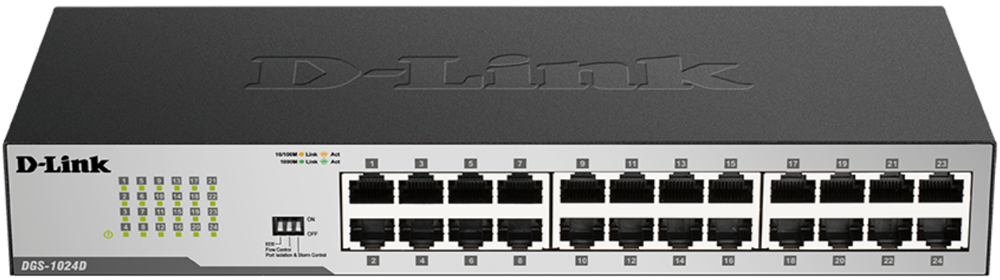
DGS-1024D
24-Port Gigabit Unmanaged Switch 24 10/100/1000Base-T

About This Guide
The D-Link DGS-1024D 24-Port Gigabit Desktop Switch is a stand-alone plug-and-play device. This Quick Installation Guide gives step-by-step instructions for setting up the device. The model you have purchased may appear slightly different from the images shown in this guide. For more detailed information about the switch, installation process, making network connections, and technical specifications, please refer to the User Manual or visit http://www.dlink.com
Package Contents
These are the items included with your purchase:
- DGS-1024D 24-Port 10/100/1000Base-T Gigabit Ethernet Switch
- AC power cord
- Four rubber feet
- Screws and two mounting brackets
- Quick Install Guide
- Power cord retainer
- Tie wrap
If any of the above items are missing, please contact your D-Link reseller for replacement.
Before Connecting to the Network
As with any electronic device, you should place the equipment where it will not be subjected to extreme temperatures, humidity, or electromagnetic interference. Specifically, the site you select should meet the following requirements:
A. Install the DGS-1024D in a fairly cool and dry place. See the Technical Specifications page in the manual for the acceptable operating temperature and humidity ranges.
B. Install the switch in a site free from vibration, dust, and direct sunlight.
C. Leave at least 10cm of space on the left and right-hand sides of the switch for ventilation.
D. Visually inspect the power cable and ensure that it is firmly inserted into a suitable power outlet.
Switch Installation
The DGS-1024D can easily be mounted in an EIA standard-size 19-inch rack which can be placed in a wiring closet with other equipment or placed on a desktop or shelf.
Desktop or Shelf Installation
When installing the switch on a desktop or shelf, use the rubber feet provided. Position and apply the rubber feet to the bottom corners of the DGS-1024D switch.

Rack Installation
To install in a rack, attach the mounting brackets to the switch’s side panels (one on each side) and secure them with the screws provided. Then, use the hardware provided with the equipment rack to mount the switch in the rack.


Installing a Power Cord Retainer
Installation of a power cord retainer is recommended to prevent accidental removal of the AC power cord.
A. Insert a tie wrap with the rough side facing down into the hole below the power socket.

Insert tie wrap
B. Connect the AC power cord into the AC power inlet of the switch.

C. Attach the retainer to the tie wrap and slide it up to the end of the cord.

D. Wrap the retainer around the power cord and place the free end into the fastener.

Wrap the retainer around the power cord
E. Fasten the retainer by pulling on it until secure.

Connect the power cord to the switch
F. Connect the AC power cord to an electrical outlet.
Connecting the DGS-1024D to your network
A. Power
The switch can be used with AC power sources 100 – 240 VAC, 50 – 60 Hz. The switch’s power supply will adjust to the local power source automatically and may be turned on without having any or all LAN segment cables connected.
B. Ethernet
These ports support network speeds of 10 Mbps, 100 Mbps, or 1000 Mbps, and can operate in half-duplex and full-duplex transfer modes. These ports also support automatic MDI/MDIX crossover detection, which gives the switch true “plug and play” capabilities. Just connect any network cable between the switch and the device, and the switch will automatically detect the settings of the device and adjust itself accordingly.
LED Indicators

The LED indicators allow you to monitor, diagnose, and troubleshoot potential problems with the switch, connection, or attached devices.
| LED | Color | State | Indication |
| Power | Green | Light on | Power on |
| Light of | Power off | ||
| Link/Act/ Speed | Green | On | Connection (or link) at 1000 Mbps |
| Blinking | Reception or Transmission at 1000 Mbps | ||
| Anther | On | Connection (or link) at 10/100 Mbps | |
| Blinking | Reception or Transmission at 10/100 Mbps |
Cable Diagnostics (During Boot Only)
| Port Link/Act/ Speed LED Color | Status |
| Green | No Faults Detected /Good Cable Connection |
| Amber | Open or Short Circuit |
DIP Switches

The DIP switches on the front panel allow easy configuration of the advanced features of the DGS1024D.
| DIP Switch |
Function Controlled | Default |
| EEE | Enables/Disable IEEE 802. az Energy-Efficient Ethernet Feature | On |
| Flow Control |
Enables/Disable Flow Control Feature | On |
| Port Isolation and Storm Control |
Port Isolation: See Below Storm Control: When enabled, a broadcast storm control threshold value of 128 kbps will be applied to incoming broadcast packets on all ports. |
Off |
Port Isolation:
When enabled, ports 1 to 23 will be isolated from each other, but will still be able to communicate with port 24. Port 24 will be able to communicate with all the ports available on this switch.
Note: The switch must be power cycled after changing DIP Switch settings for new settings to take effect.
Additional Information
Additional help and product information are available online at http://www.dlink.com.
Warranty Information
Please visit http://warranty.dlink.com/ for warranty information for your region.
©2020 D-Link Corporation. All rights reserved. Trademarks or registered trademarks are the property of their respective holders. Software and specifications are subject to change without notice.
