D-Link DAP-3666 Nuclias Connect AC1200 Wave 2 Outdoor Access Point Installation Guide
D-Link DAP-3666 Nuclias Connect AC1200 Wave 2 Outdoor Access Point Installation Guide

Before You Begin
This installation guide provides instructions for installing the DAP-3666 on your network. Additional documentation is also available on the D-Link support website.
- Nuclias Connect Manual: For additional information and instructions on how to configure the device using Nuclias Connect.
- DAP-3666 User Manual: For additional information and instructions on how to configure the device using the web user interface.
Package Contents
This DAP-3666 package includes the following items:
- DAP-3666 Access Point
- Mounting Plate and Hardware
- Grounding Wire
- Quick Start Guide
- Mounting kit (Wall/Pole Mount)
- Stainless steel mount base x 1
- Stainless tie back straps x 2
- Wall screw x 4
- Wall plug x4
- Stainless mount screw (hexagonal hole) x1
If any of the above items are damaged or missing, please contact your local D-Link reseller.
Note: To power the unit, use an 802.3af or 802.3at PoE Switch or PoE Injector.
System Requirements
- Computers with Windows®, Macintosh®, or Linux-based operating systems with an installed Ethernet Adapter
- Internet Explorer 11, Safari 7, Firefox 28, or Google Chrome 33 and above (for configuration)
Hardware Overview
LED Indicators
Figure 1: Front Panel LED
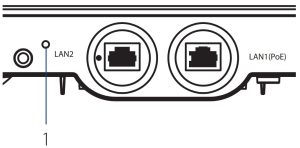

Table 1: LED Description
# |
LED |
Description |
1 |
Power/ Status |
Green (Solid) – Device operational Red (Flashing) – Device booting up/Device malfunctioned Red (Solid) – Device boot up has failed |
Interface Connectors
- Figure 2: Bottom Connectors

- Table 2: Interface Description
#
Connector
Description
1
Mounting Lock
Connector for the mount screw.
2
Reset
Press and hold for 10 seconds to factory reset the device.
3
LAN2 Port
Gigabit RJ-45 port for data.
4
LAN1(PoE) Port
Port Gigabit RJ-45 port for data and Power over Ethernet (PoE) power.
- Figure 3: Rear Connectors
- Table 3: Interface Description
#
Connector Description 1
Grounding Wire
Connector for the grounding wire.
2 Wall/Pole Mount Mount to connect to the mounting plate on a wall or a pole.
Installation
Using Power over Ethernet (PoE)
- Use a standard Ethernet cable to connect the LAN1(PoE) port on the DAP-3666 to a PoE power source device such as an 802.3af or 802.3at PoE switch or PoE injector.
Configuration
Using Nuclias Connect
The DAP-3666 is designed to be managed through Nuclias Connect. Refer to the Nuclias
Connect Manual for detailed configuration instructions.
Note: D-Link recommends manually configuring the device before mounting it.Nuclias Connect App Configuration
- Download the free Nuclias Connect app from the App Store or Google Play by searching for Nuclias Connect or by scanning the QR code below.
- Open the Nuclias Connect app and follow the onscreen instructions to discover and set up your device.
Manual Configuration
Note: The management computer, DHCP server and DAP-3666 must be in the same subnet.
Use one of the following methods to access the web user interface:Connecting through Ethernet
- Use an Ethernet cable to connect the DAP-3666 to the management computer, or to the switch or router the management computer is connected to.
- Manage the access point from a computer. Enter dap3666.local in the address field of your browser.
- Log in to the administration user interface. The default login information is
Username: admin
Password: admin
Mounting
- Figure 4: LAN Port Waterproof Enclosure
- Connect an Ethernet Cable to the LAN1(PoE) port on the DAP-3666. Use the LAN Port Waterproof Enclosures to seal the ports.
Mounting on a Pole
- Figure 5: Attaching the Mounting Plate
- Secure mount base to the pole with the two stainless tie back strap sets. Ensure that the tie back is locked securely.
- Figure 6: Mounting the Device
- Figure 6: Mounting the Device
- Align and slide the DAP-3666 down so that the mounting plate securely locks to the DAP-3666.
Mounting on a Solid Wall
- Figure 7: Attaching the Mounting Plate
- Use the mounting plate to mark the location where to drill the holes in the wall.
- Drill holes on the markings and place the included anchors into the drilled holes.
- Align and place the mounting plate on top of the anchors and use the included screws to secure the mounting plate to the surface.
- Figure 8: Mounting the Device
- Figure 8: Mounting the Device
- Align and slide the DAP-3666 down so that the mounting plate securely locks to the DAP-3666.
Securing the Mount Screw and Connecting the Grounding Wire
- Figure 9: Attaching the Mount Screw
- Use the included mount screw (hexagonal hole) to lock the DAP-3666 to the pole/ wall mount.
- Figure 10: Securing the Mount Screw
- Figure 10: Securing the Mount Screw
- With the included hexagon socket spanner, tighten the mount screw until the DAP-3666 is secured.
- Figure 11: Attaching the Grounding Wire
- Figure 11: Attaching the Grounding Wire
- A grounding wire is to protect your device from lightning strikes and the buildup of static electricity. Attach the grounding wire to the DAP-3666 using the included screw(M3.9 * 7.8 mm).
- Figure 12: Attaching the Grounding Wire
- Figure 12: Attaching the Grounding Wire
- Tighten the grounding wire (green-andyellow, 18AWG) to the DAP 3666 until it is securely attached.
- Figure 13: Attaching the Grounding Wire
- Figure 13: Attaching the Grounding Wire
- Attach the other end of the grounding wire to either the wall or pole mount. Ensure that the wall or pole mount is connected to an electrical ground.
Appendix – Statements
ErP Power Usage
This device is an Energy Related Product (ErP) that automatically switches to a power-saving Network
Standby mode within 1 minute of no packets being transmitted. It can also be turned off through a power switch to save energy when it is not needed.
Network Standby: 5.84 wattsFederal Communication Commission Interference Statement
This device complies with Part 15 of the FCC Rules. Operation is subject to the following two conditions: (1) This device may not cause harmful interference, and (2) this device must accept any interference received, including interference that may cause undesired operation.
This equipment has been tested and found to comply with the limits for a Class B digital device, pursuant to Part 15 of the FCC Rules. These limits are designed to provide reasonable protection against harmful interference in a residential installation. This equipment generates, uses and can radiate radio frequency energy and, if not installed and used in accordance with the instructions, may cause harmful interference to radio communications. However, there is no guarantee that interference will not occur in a particular installation. If this equipment does cause harmful interference to radio or television reception, which can be determined by turning the equipment off and on, the user is encouraged to try to correct the interference by one of the following measures:- Reorient or relocate the receiving antenna.
- Increase the separation between the equipment and receiver.
- Connect the equipment into an outlet on a circuit different from that to which the receiver is connected.
- Consult the dealer or an experienced radio/TV technician for help
FCC Caution:
- Any changes or modifications not expressly approved by the party responsible for compliance could void the user’s authority to operate this equipment.
- This transmitter must not be co-located or operating in conjunction with any other antenna or transmitter.
Radiation Exposure Statement:
This equipment complies with FCC radiation exposure limits set forth for an uncontrolled environment. This equipment should be installed and operated with minimum distance 20cm between the radiator & your body.
Note: The country code selection is for non-US model only and is not available to all US model. Per FCC regulation, all WiFi product marketed in US must fixed to US operation channels only.Japan Voluntary Control Council for Interference Statement
This is a Class B product based on the standard of the VCCI Council. If this is used near a radio or television receiver in a domestic environment, it may cause radio interference. Install and use the equipment according to the instruction manual.Product and Warranty Information
To find out more about D-Link Nuclias product or marketing information, please visit the website http://www.dlink.com or https://www.nuclias.com.
The D-Link Limited Lifetime Warranty information is available at
http://www.dlink.com/warrantyVCCI-B
- Instructions for the installation of that conductor to building earth by a SKILLED PERSON.
- Please contact the authorized distributor of D-Link for related accessories (Outdoor interconnection cable, Cable Gland, Cable, etc.) for purchase and installation.
Ver. 1.03(WW)_130x183
2020/03/06
5300-00007657-01W


