D-Link Gigabit Desktop Switch Installation Guide

Gigabit Desktop Switch


This document will guide you through the basic installation process for your new D-Link Gigabit Desktop Switch. DGS-1016D/DGS-1024D
Getting Started Guide
About This Guide
The D-Link DGS-1016D/1024D 16/24-Port Gigabit Desktop Switch is a stand-alone plug-and-play device. This Quick Installation Guide gives step- bystep instructions for setting up the device. The model you have purchased may appear slightly different from the images shown in this guide. For more detailed information about the switch, installation process, making network connections, and technical specifications, please refer to the User Manual or visit http://www.dlink.com
Package Contents
These are the items included with your purchase:
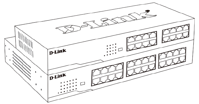
- D-Link DGS-1016D 16-Port or DGS-1024D 24-Port 10/100/1000BASE-T Gigabit Ethernet Switch
- AC power cord
- Four rubber feet
- Screws and two mounting brackets
- Quick Installation Guide
- Power cord retainer
- Tie wrap
If any of the above items are missing, please contact your D-Link reseller for replacement.
Switch Installation
The DGS-1016D/1024D can easily be mounted in an EIA standard-size 19-inch rack which can be placed in a wiring closet with other equipment or placed on a desktop or shelf.
Desktop or Shelf Installation
When installing the switch on a desktop or shelf, usethe rubber feet provided. Position and apply the rubberfeet to the bottom corners of the DGS-1016D/1024Dswitch.

Rack Installation
To install in a rack, attach the mounting brackets to the switch’s side panels (one on each side) and secure them with the screws provided. Then, use the hardware provided with the equipment rack to mount the switch in the rack.


Installing a Power Cord Retainer
Installation of a power cord retainer is recommended to prevent accidental removal of the AC power cord.
A. Insert a tie wrap with the rough side facing down into the hole below the power socket.

B. Connect the AC power cord into the AC power inlet of the switch.

Connect the power cord to the switch
C. Attach the retainer to the tie wrap and slide it up to the end of the cord.

Attach the retainer to the tie wrap
D. Wrap the retainer around the power cord and place the free end into the fastener.

Wrap the retainer around the power cord
E. Fasten the retainer by pulling on it until secure.
Secure the power cord
F. Connect the AC power cord to an electrical outlet.
LED Indicators

The LED indicators allow you to monitor, diagnose, and troubleshoot potential problems with the switch, connection, or attached devices.
| LED | Color | State | Indication |
| Power | Green | Light on | Power on |
| Light off | Power off | ||
| Link/Act/ Speed | Green | On | Connection (or link) at 1000 Mbps |
| Blinking | Reception or Transmission at 1000 Mbps | ||
| Amber | On | Connection (or link) at 10/100 Mbps | |
| Blinking | Reception or Transmission at 10/100 Mbps |
Cable Diagnostics (During Boot Only)
| Port Link/Act/ Speed LED Color | Status |
| Green | No Faults Detected /Good Cable Connection |
| Amber | Open or Short Circuit |
DIP Switches

The DIP switches on the front panel allow easy configuration of the advanced features of the DGS1016D and DGS-1024D.
DIP Switch |
Functio n Controlled | Default |
| EEE | Enables/Disable IEEE 802.az Energy-Efficient Ethernet Feature | On |
| Flow Control | Enables/Disable Flow Control Feature | On |
| Port Isolation and Storm Control | Port Isolation: See Below Storm Control: When enabled, a broadcast storm control threshold value of 128 kbps will be applied to incoming broadcast packets on all ports. | Off |
Port Isolation:
DGS-1016D – When enabled, ports 1 to 15 will be isolated from each other, but will still be able to communicate with port 16. Port 16 will be able to communicate with all the ports available on this switch.
DGS-1024D – When enabled, ports 1 to 23 will be isolated from each other, but will still be able to communaicate with port 24. Port 24 will be able to communicate with all the ports available on this switch.
Note: The switch must be power cycled after changing DIP Switch settings for new settings to take effect.
Additional Information
Additional help and product information is available online at http://www.dlink.com.
Warranty Information
Please visit http://warranty.dlink.com/ for warranty
information for your region.
©2020 D-Link Corporation. All rights reserved.
Trademarks or registered trademarks are the property of their respective holders. Software and specifications subject to change without notice.
2020/03/09
