Dell Cabling instructions for 48V – 60V DC power supply Instructions
DELL Cabling instructions for 48V – 60V DC power supply Instructions

Cabling instructions for – (48 – 60) V DC power supply
Notes, Cautions, and Warnings
NOTE: A NOTE indicates important information that helps you make better use of your product.
CAUTION: A CAUTION indicates either potential damage to hardware or loss of data and tells you how to avoid the problem.
WARNING: A WARNING indicates a potential for property damage, personal injury, or death.
This document describes the requirements and power and safety ground cable wiring instructions for systems equipped with a – (48–60) V DC power supply.
CAUTION:
- This installation should only be done by a certified service technician. You should only perform troubleshooting and simple repairs as authorized in your product documentation, or as directed by the online or telephone service and support team. Damage due to servicing that is not authorized by Dell is not covered by your warranty. Read and follow the safety instructions that are shipped with your product.
- Wire the unit with copper only (unless otherwise specified), 10 American Wire Gauge (AWG) wire rated minimum 90°C in parallel for source and return.
- Protect the – (48–60) V (1 wire) with a branch circuit overcurrent protection rated 30 A rated for DC with a high interrupt current rating.
- Connect the equipment to a – (48–60) V DC SELV supply source that is electrically isolated from the AC source.
- Ensure that the – (48–60) V DC source is efficiently secured to earth (ground).
- A readily accessible disconnect device that is suitably approved and rated shall be incorporated in the field wiring.
Input Requirements:
Supply voltage: – (48–60) V DC
Current consumption: 27 A maximum
Kit Contents: Plug with crimping lugs (1) – Dell Part # RN5T2
Required Tools
Wire-stripper Pliers (YQK-70.DELIXI) or equivalent crimping tool capable of removing insulation from 10 AWG, solid or stranded, insulated copper wire (alpha wire part #3080 or
equivalent 65/30 stranding).
- One UL 1015 10 AWG, 2 m maximum (stranded) black wire (– (48–60) V DC)
- One UL 1015 10 AWG, 2 m maximum (stranded) red wire (VDC return)
- One UL 1015 10 AWG, 2 m maximum green/yellow, green with a yellow stripe, stranded wire (safety ground)
- NOTE: This product is intended to be used in CBN (Common Bonding Network) applications. Strip the insulation from the end of the green/yellow wire, exposing approximately
4.5 mm (0.175 inches) of copper wire. - Using a hand-crimping tool, crimp the ring-tongue terminal of M4 stud size (not supplied as part of the Kit) and suitable for 10 AWG insulated copper wire to the
green/yellow wire. - Remove the M4 nut and associated hardware from grounding post / stud.
- Connect the safety ground to the grounding post / stud on the PSUs (back of the system) using the M4 nut, Spring Washer and Locking / Star Washer.
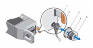
- Green / Yellow safety ground wire 2. Grounding post / stud
- Locking / star washer 4. Spring washer
- M4 Nut

NOTE: The system shown above is indicative only and may not match the actual system that you purchased.
2. Assembling the DC power cable

- Cap on plug
- Screws on the plug
- Input plug
- Crimp terminals
- Heat shrink tubing
- 10 AWG red wire
- 10 AWG black wire
To construct the DC input power cable, perform the following steps:
- Strip the insulation from the ends of the DC power wires such that ends are exposed to match the crimp terminal.
- Twist and reshape the exposed stranded wires.
- Crimp 10 AWG black and 10 AWG red wires into crimp terminals using hand-crimping tool.
- Insert suitable heat shrink tubing (not supplied as part of the kit) over each crimp terminal head so that covers the length of the barrel and extend approximately about an inch on the wires.
- Using a heat gun or suitable tool shrink the tubing so it sits snug on the barrel and wire.
- Insert the black wire into connector housing position marked -48 V.
- Insert the red wire into connector housing position marked RTN.
- Secure both black and red wires into the input plug using the screws and insert the cap over the screws. The screw is intended to go through the hole in the crimp lug. Ensure that the cap is inserted properly and the crimp lug is secured with the screw by lightly tugging at the cables.
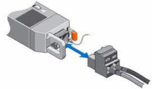
3. Connecting the – (48–60) V DC power cable
- To connect the – (48–60) VDC power cable, plug the – (48–60) V DC power cable into the system.
- Insert DC cable assembly into PSU side connector.
