Dell SE2422H 24 Full HD Computer Installation Guide

DELL SE2422H


  1. Disassembly Procedures:
    S1 Open the Pizza carton with a proper tool.
    S2 Take out all of the accessories including QSG, HDMI cable, power cable, CD&user’s manual, stand base, stand riser and EEI label from the carton. (Note: It depends on whether users returning the accessories)
    S3 Take out of the paper top with base, riser and cover from the carton, then take out the monitor from the EPE bag and put it on a protective cushion.
    S4 Use a Philips-head screwdriver to remove 6pcs screws for unlocking mechanisms.
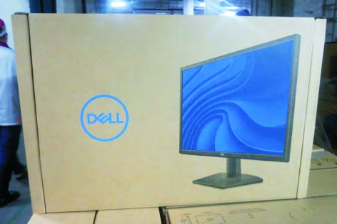
    (No.1~4 screw size=M4x11; Torque=11±1kgfxcm;
    No.5~6 screw size=M4x6; Torque=11±1kgfxcm)
    S5 
    Turn over the LCD monitor to let the screen faced up, place a cloth on the panel where you are working on to protect the panel. Continually, wedge your fingers between the front bezel and the panel in order of arrow preference for unlocking mechanisms. Turn over the LCD monitor to let the screen faced down and then remove the rear cover.
    S6 Disconnect the function key cable away from the  connector of the board, then tear off 3pcs adhesive tape for releasing the function key board.
    S7 Tear off 2pcs aluminum foils for unlocking panel lamp cable and LVDS cable, and then disconnect the panel lamp cable away from the connector of panel module.
    S8 Use a Philips-head screwdriver to remove 2pcs screws for unlocking the bracket with panel module. Use a Hex-head screwdriver to remove 2pcs screws for unlocking the VGA connector.
    (No.1~2 screw size=M3x2.6, Torque=4±0.5kgfxcm;
    No.3~4 screw size=M3x8, Torque=6±0.5kgfxcm)
    S9 Unplug the LVDS cable from the connector of the panel module by pushing the earing-locks.
    S10 Lift up the bracket chassis and put it on a protective cushion.
    S11 Release the panel module away from the hooks of the front bezel, then lift up the panel module and take away the front bezel with keyboard.
    S12 Tear off the mylar tape, then put the front bezel into a fixture, then use a Philips-head screwdriver to remove 3pcs screws for unlocking the function key board with the front bezel.
    (No.1~3 screw size=M2x2.4, Torque=0.8±0.2kgfxcm
    S13 Remove the Mylar from the hooks of the bracket chassis module.
    S14 Use a Philips-head screwdriver to remove 4pcs screws for unlocking the circuit board, release all the cables from the hooks.
    (No.1 screw size=M4x8, Torque=6±0.5kgfxcm;
    No. 2~4 screw size=M3x7.5, Torque=6±0.5kgfxcm)
    S15 Remove the interface board and power board from the bracket chassis module carefully, and disconnect all the cables.
    S16 Remove electrolyte capacitors (red mark) from printed circuit boards.
    S16-1 Cut the glue between bulk cap. and PCB with a knife.
    S16-2 Ensure cutting path within the glue, don’t touch bulk cap. or PCB.
    S16-3 Cut into the bottom of bulk cap. and pullit up carefully.
    S16-4 Take out bulk cap. pin solder with soldering iron and absorber.
    S16-5 Lift the bulk cap. up and away from the PCB.
  2. Product material information
    The following substances, preparations, or components should be disposed of or recovered separately from other WEEE in compliance with Article 4 of EU Council Directive 75/442/EEC.
    Capacitors / condensers (containing PCB/PCT) No used
    Mercury containing components No used
    Batteries No used
    Printed circuit boards (with a surface greater than 10 square cm) Product has printed circuit boards (with a surface greater than 10 square cm)
    Component contain toner, ink and liquids No used
    Plastic containing BFR No used
    Component and waste contain asbestos No used
    CRT No used
    Component contain CFC, HCFC, HFC and HC No used
    Gas discharge lamps No used
    LCD display > 100 cm2 Product has an LCD greater than 100 cm2
    External electric cable Product has external cables
    Component contain refractory ceramic fibers No used
    Component contain radio-active substances No used
    Electrolyte capacitors (height > 25mm, diameter > 25mm) Product has electrolyte capacitors (height > 25mm, diameter > 25mm)
  3. Tools Required List the type and size of the tools that would typically can be used to disassemble the product to a point where components and materials requiring selective treatment can be removed. Tool Description:
    • Screwdriver (Phillip head) #1
    • Screwdriver (Phillip head) #2
    • Penknife
    • Soldering iron and absorber