Dell S2721HN 27 inch Monitor User Guide
DELL S2721HN 27 inch Monitor User Guide
1. Important Safety Notice
Product Announcement:
This product is certificated to meet RoHS Directive and Lead-Free produced definition. Using approved critical components only is recommended when the situation to replace defective parts. Vender assumes no liability express or implied, arising out of any unauthorized modification of design or replacing non-RoHS parts. Service providers assume all liability.
Qualified Reparability:
Proper service and repair is important to the safe, reliable operation of all series products. The service providers recommended by vender should be aware of notices listed in this service manual in order to minimize the risk of personal injury when perform service procedures. Furthermore, the possible existed improper repairing method may damage equipment or products. It is recommended that service engineers should have repairing knowledge, experience, as well as appropriate product training per new model before performing the service procedures.
NOTICE:
! To avoid electrical shocks, the products should be connected to an authorized power cord, and turn off the master power switch each time before removing the AC power cord.
! To prevent the product away from water or expose in extremely high humility environment.
! To ensure the continued reliability of this product, use only original manufacturer’s specified parts.
! To ensure following safety repairing behavior, put the replaced part on the components side of PWBA, not solder side.
! To ensure using a proper screwdriver, follow the torque and force listed in assembly and disassembly procedures to unscrew screws.
! Using Lead-Free solder to well mounted the parts.
! The fusion point of Lead-Free solder requested in the degree of
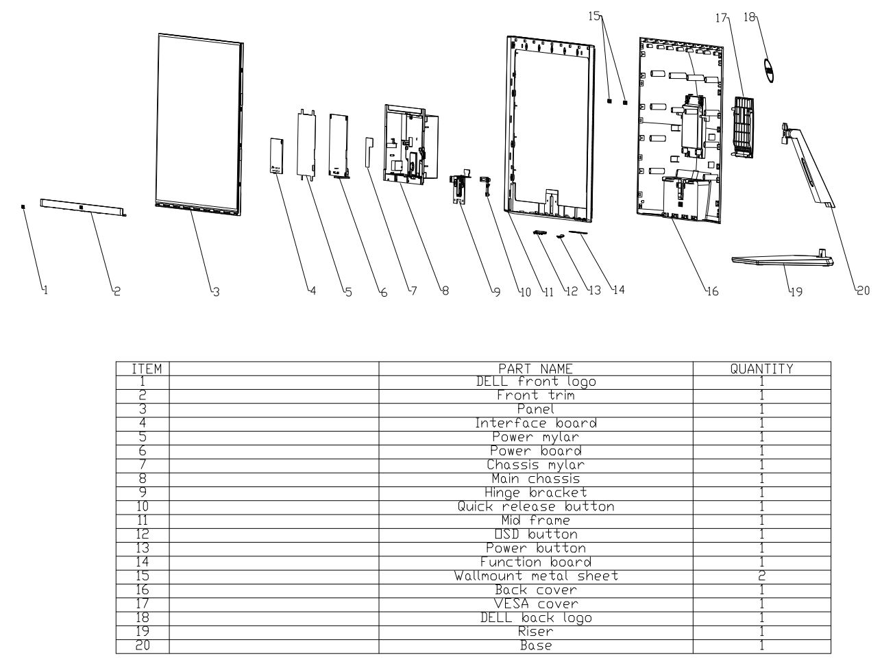
2. Exploded view diagram with list of items

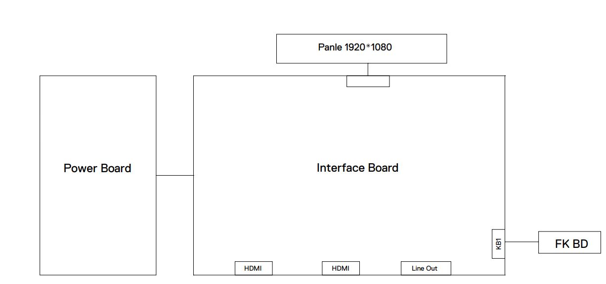
3. Wiring Connectivity Diagram

4. Disassembly and Assembly Procedures
Necessary repair and test equipment:
1. Philips-head screwdriver
4.1 Disassembly Procedures:
Remove the monitor stand base:
(S1)
- Place the monitor on a soft cloth or cushion. Press the stand down to access to the release latch.
- Use a long screwdriver to press the release latch. While pressing the release latch, slide out the stand assembly from the monitor.

(S2) To remove the VESA cover: Press the dimple on the VESA cover to release it from the back of the display.

(S3) Use a Philips-head screwdriver to remove 6pcs screws for unlocking mechanisms.

(S4) Use one hand to press the rear cover, then wedge your fingers between the rear cover and the middle bezel on the corners of the top left side to the right side of the monitor to release the rear cover.


(S5) Tear off 1pcs acetate tape and then disconnect the panel lamp cable away from the connector of panel. Tear off 2pcs aluminum foils, and then disconnect the function key cable away from the connector of the board.

(S6) Use a Philips-head screwdriver to remove 18pcs screws for unlocking the middle bezel.

(S7) Use a Philips-head screwdriver to remove 2pcs screws for unlocking the bracket with middle bezel, to remove 2pcs screws for unlocking the bracket with panel module.

Take away the middle bezel, and put it on a fixture. Use a Philips-head screwdriver to remove 3pcs
(S8) screws for unlocking the function key board with the middle bezel, and then tear off the tapes for releasing the key cables.

(S9) Tear off the tape, then lift up the panel module with the bracket chassis for releasing the front bezel away from the panel module.

(S10) Unplug the LVDS cable from the connector of the panel module by pushing the earing-locks.

(S11) Take away the bracket chassis module and then put the bracket chassis module on a protective cushion.

(S12) Remove the Mylar from the hooks of the bracket chassis module.

(S13)
Use a Philips-head screwdriver to remove 5pcs screws for unlocking the circuit board, release all the cables from the hooks.


(S14) Remove the interface board and power board from the bracket chassis module carefully, and disconnect all the cables.

4.2 Assembly Procedures:
(S1) Place a bracket chassis base on a protective cushion.

(S2) Turn over a power board and put the power board into the bracket chassis, locate the panel power cable into the hook of the bracket chassis.

(S3) Take a interface board, connect a LVDS cable to the connector of the interface board, then connect the cable of the power board to the connector of the interface board. Turn over the interface board and
locate it into the bracket. Use a Philips-head screwdriver to tighten 5pcs screws for locking the power board and interface board.

(S5) Take a Mylar to insert the hooks of the bracket to cover the power board.
(S6) Panel preparation: Take out 1pcs panel module from the carton, then remove the protective film by tearing off the tapes, and then examine the panel surface according to inspection criteria. Turn over the panel, and then place screen faced down for later assembling.

(S7) Move the bracket close to the panel, then connect LVDS cable to the connector of the panel. Turn over the bracket and put it on the back of panel. Paste 1pcs tape to cover the LVDS connector.

(S8) Take 1pcs front bezel, then lift up the panel with bracket and assemble the front bezel with the panel module.
(S9) Take a function key board and a middle bezel, then fix the middle bezel with a fixture, and locate the function keyboard into the hooks of the bezel. Use a Philips-head screwdriver to tighten 3pcs screws for locking the function key board with the middle bezel.

(S10)
Move the middle bezel with function key board close to the panel unit, tear off the papers of the tapes on the back of the key cable, and then fix the key cable on the bezel by 1pcs tape, then assemble the middle bezel with the front bezel and panel module.

(S11) Use a Philips-head screwdriver to tighten 2pcs screws for locking the bracket with middle bezel, to tighten 2pcs screws for locking the bracket with panel.

(S12)
Use a Philips-head screwdriver to lock 13pcs screws for locking the middle bezel with the panel module, then lock 5pcs screws for locking the middle bezel with front bezel.

(S13)
Connect the function key cable to the connector of board, then paste 2pcs aluminum foils on the specific positions as the picture below shown.

(S14)
Connect the panel lamp cable to the connector of panel, then paste 1pcs acetate tape to cover the panel lamp connector.


(S15)
Take 1pcs rear cover, put down the rear cover and push the rear cover on the positions marked as the picture below shown for mechanisms engagement.

(S16)
Use a Philips-head screwdriver to tighten 4pcs screws for locking rear cover with the assembled unit, to tighten 2pcs screws for locking the rear cover with bracket chassis module.

(S17)
Stick 2pcs labels on the specific positions as the picture below shown. Take 1pcs stand riser and 1pcs stand base, assemble the stand base with stand riser, then rotate the screw clockwise to lock the stand base and stand riser. Insert the stand-riser into monitor groove until it snaps into its place.

(S18)
Lift up the monitor to checking the gap between the front bezel with panel module , then provide power supply and a video signal to the monitor, then turn on the monitor for functionality check.

5. Trouble Shooting Instructions
Self-test
Your monitor provides a self-test feature that allows you to check whether your monitor is functioning properly. If your monitor and computer are properly connected but the monitor screen remains dark, run the monitor self-test by performing the following steps:
- Turn off both your computer and the monitor.
- Unplug the video cable from the back of the computer. To ensure proper Self-Test operation, remove all video cables from the back of computer.
- Turn on the monitor.
The floating dialog box should appear on-screen (against a black background), if the monitor cannot sense a video signal and is working correctly. While in self-test mode, the power LED remains white. Also, depending upon the selected input, one of the dialogs shown below will continuously scroll through the screen. - This box also appears during normal system operation if the video cable is disconnected or damaged.
- Turn off your monitor and reconnect the video cable; then turn on both your computer and the monitor.

www.dell.com/support/S2421HN
www.dell.com/support/S2421NX
If your monitor screen remains blank after you use the previous procedure, check your video controller and computer, because your monitor is functioning properly.
Built-in diagnostics
Your monitor has a built-in diagnostic tool that helps you determine if the screen abnormality you are experiencing is an inherent problem with your monitor, or with your computer and video card.
To run the built-in diagnostics:

- Ensure that the screen is clean (no dust particles on the surface of the screen).
- Press and hold Button 4 for four seconds, a menu appears on the screen.
- Select the built-in diagnostics
- Carefully inspect the screen for abnormalities.
- Press Button 1 on the front panel again. The color of the screen changes to red.
- Inspect the display for any abnormalities.
- Repeat steps 5 to 6 to inspect the display when it changes to green, blue, black, white, and text screens.

The test is complete when the text screen appears. To exit, press Button 1 again. If you do not detect any screen abnormalities during the built-in diagnostic tool, the monitor is functioning properly. Check the video card and computer.
Common problems
The following table contains general information about common monitor problems you might encounter and the possible solutions.


https://www.dell.com/support/monitors.
Product specific problems
