VIKING K-1705-IP Series VoIP Entry
Phone System User Manual
VIKING K-1705-IP Series VoIP Entry Phone System User Manual


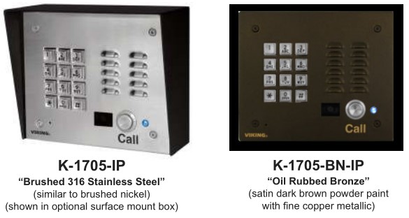

The K-1705-IP Series entry phones provide a durable and attractive hands-free phone for apartment and residential door entry or applications requiring a vandal resistant VoIP speaker phone with an integrated analog Color Video Camera. The K-1705-IP phone is designed to provide quick and reliable hands-free communication for SIP VoIP phone systems with PoE. The unit can be programmed from any PC on the same LAN or remotely using a Static IP Address. The K-1705-IP entry phone can dial up to 250 programmable numbers and another 250 rollover numbers and provide CCTV video of the entry area. They are available in two attractive finishes: “Brushed Stainless Steel” and “Oil Rubbed Bronze”.
When the K-1705-IP phone is connected to an apartment or business tenant, a built-in contact closure may be activated to control an electric gate or door strike. Up to 1,000 keyless entry codes may be programmed, providing tenants with keyless entry. A 26 Bit Wiegand input is provided for adding an optional proximity card reader with capacity to program up to 1,000 card numbers. Keyless entry codes and card numbers can be programmed to only allow access at specific times and/or day of the week. The K-1705-IP includes a request for exit (REX) input and also offers activity logging.

The K-1705-IP-EWP shares all of the features of the K-1705-IP in addition to Enhanced Weather Protection (EWP) for outdoor installations where the unit is exposed to precipitation or condensation. EWP products are designed to meet IP66 standards and may feature foam rubber gaskets, sealed connections, gel-filled butt connectors, as well as potted circuit boards. For more information on EWP, see DOD 859 .
Features
- Vandal Resistant Features: 14 gauge louvered 316 stainless steel faceplate with permanent laser etched graphics. Speaker/mic screen. Heavy duty metal keypad and “Call” button. Scratch resistant powder coating (K-1705-BN-IP). T-10 Security Torx drive mounting screws.
- Weather Resistant Features: Marine grade 316 stainless steel faceplate, screws and push button switch. Switch internally sealed per IP67. Mylar speaker. Selfdraining mic mount. Faceplate, mic and speaker gaskets. Weather resistant powder paint (K-1705-BN-IP)
- Available in 2 standard finishes: 316 brushed stainless steel with laser etched graphics or oil rubbed bronze powder paint with copper metallic graphics
- Built-in high resolution analog NTSC color video camera with wide viewing angle, tilt/swivel adjustments and wide operating temperature: -40°F to 140°F
- Two sets of SPDT 2 Amp relay contacts for door/gate or camera control
- Optional RC-4A for Secure Remote Relay Control, see DOD 582
- Blue “Call /Status” LED indicator · SIP compliant (see page 2 for compatible SIP servers and IP phone systems)
- PoE powered (class 2, <6.5 watts) · Automatic Noise Canceling (ANC) feature for operation in noisy environments
- Viking’s proprietary VOX switching eliminates the need for “Push to Talk” mode
- Network downloadable firmware
- 26 Bit Wiegand input for optional proximity card readers, see DOD 221 and 228
- 26 Bit Wiegand output connect to card reader input of an Access Control System
- Programmable to speed dial up to 250 numbers
- Cycles to roll over phone number on busy or no-answer
- Program up to 1,000 keyless entry codes and/or proximity card numbers
- Keyless entry codes and proximity card numbers can be programmed to only allow access at specific times and day of week
- Event logging with time and date stamp
- Optional Enhanced Weather Protection (EWP) available – EWP products are designed to meet IP66 Ingress Protection Rating, see DOD 859
- Hangs up on busy signal, time-out or touch tone command
- Remotely programmable
- Extended temperature range (-40°F to 140°F)
- Programmable volume adjustments for microphone and speaker
- Selectable auto-answer feature for monitoring
- Flush mount with included steel rough-in box, or use an optional VE-6×7 surface mount box (not included, see DOD 424)
- Optional VE-LIGHT kit to illuminate the front panel at night, see DOD 428
- Diagnostics (for testing mic, speaker and relays)
Applications
- Apartment Entry Phone
- Residential Gate Entrance
- Door Entry Phone
- Courtesy Assistance Phone
- Customer Service Phone
- Automated Teller (ATM) Phone
- Security or Emergency Phone
- Hot-Line Phone
- Kiosk Phone with up to 250 number speed dialing
Information: 715-386-8861
www.VikingElectronics.com
Specifications
Power: PoE class 2 (<6.5 watts)
Dimensions:
Overall: 5.5″ x 6.5″ x 2.6″ (140mm x 165mm x 66mm)
Rough-in box: 4.5″ x 5.5″ x 2.5″ (114mm x 140mm x 64mm)
Shipping Weight: 1.5 kg (3.3 lbs)
Operating Temperature: -40°F to 140°F (-40° C to 60° C)
Humidity – Standard Products: 5% to 95% non-condensing
Humidity – EWP Products: Up to 100%
Audio Codecs: G711u, G711a, G722
Network Compliance: IEEE 802.3 af PoE, SIP 2.0 RFC3261, 100BASE-TX with auto cross over
Regulatory Compliance: CE, FCC Part 15 and Canada ICES-003 Class A
Connections: (1) RJ45 10/100 Base-T, (14) gel-filled butt connectors
VoIP SIP System Compatibility
For compatibility and vendor specific detailed configuration instructions, see the Viking VoIP SIP System Compatibility List, DOD 944. To open and download this PDF file:
Scan the QR code below to open and download the Viking VoIP SIP System Compatibility List
– OR –
1. Go to www.vikingelectronics.com and enter 944 in the search box
2. Click Application Note (DOD 944) to open and download the PDF
Important: Exclusion from this list means only that compatibility has not been verified, it does not mean incompatibility. If you have questions, please call Viking Electronics at 715-386-8861.
Camera Specifications
Image Sensor: 1/4″ color CMOS
Video Output: 1 VP-P composite, NTSC, 75 ohms
Resolution: 420 lines (640 x 480 @ 30fps / 307,200 pixels)
Sensitivity: 0.025 LUX (50 IRE) F 1.2 3200K
Lens: 2.1mm, conical pinhole
FOV (Field of View): 80° Horizontal, 60° Vertical, 100° Diagonal
Tilt/Swivel Adjustment: Vertical +/- 20°, horizontal +/- 30° (see Diagram A)
IR Compatibility: This camera is equipped with an OLP (Optical Low Pass) filter to maintain correct video color in outside applications. The standard camera is NOT compatible with IR illuminators. If IR illumination is required, you will need to replace the existing camera with a Viking model VCAM-1IR. For more information, see DOD 190.
Maximum Wire Run Length: 1000 ft with *RG59/RG6 for video and CAT5 for power (1 pair) and entry phone audio (1 pair). 150 ft with CAT5E for video, power and entry phone audio (longer video runs are possible by using video balun transceivers.
* Note: RG59 or RG6 with solid center conductor and 95% bare copper braid shield.

Definitions
Client: A computer or device that makes use of a server. As an example, the client might request a particular file from the server.
DHCP: Dynamic Host Configuration Protocol. In this procedure the network server or router takes note of a client’s MAC address and assigns an IP address to allow the client to communicate with other devices on the network.
DNS Server: A DNS (Domain Name System) server translates domain names (ie: www.vikingelectronics.com) into an IP address.
Ethernet: Ethernet is the most commonly used LAN technology. An Ethernet Local Area Network typically uses twisted pair wires to achieve transmission speeds up to 1Gbps.
Host: A computer or device connected to a network.
Host Name: A host name is a label assigned to a device connected to a computer network that is used to identify the device in various forms of network communication.
Hosts File: A file stored in a computer that lists host names and their corresponding IP addresses with the purpose of mapping addresses to hosts or vice versa.
Internet: A worldwide system of computer networks running on IP protocol which can be accessed by individual computers or networks.
IP: Internet Protocol is the set of communications conventions that govern the way computers communicate on networks and on the Internet.
IP Address: This is the address that uniquely identifies a host on a network.
LAN: Local Area Network. A LAN is a network connecting computers and other devices within an office or building.
Lease: The amount of time a DHCP server reserves an address it has assigned. If the address isn’t used by the host for a period of time, the lease can expire and the address can be assigned to another host.
MAC Address: MAC stands for Media Access Control. A MAC address, also called a hardware address or physical address, is a unique address assigned to a device at the factory. It resides in the device’s memory and is used by routers to send network traffic to the correct IP address. You can find the MAC address of your K-1705-IP phone printed on a white label on the top surface of the PoE LAN port.
Router: A device that forwards data from one network to another. In order to send information to the right location, routers look at IP Address, MAC Address and Subnet Mask.
RTP: Real-Time Transport Protocol is an Internet protocol standard that specifies a way for programs to manage the real-time transmission of multimedia data over either unicast or multicast network services.
Server: A computer or device that fulfills requests from a client. This could involve the server sending a particular file requested by the client.
Session Initiation Protocol (SIP): Is a signaling communications protocol, widely used for controlling multimedia communication sessions such as voice and video calls over Internet Protocol (IP) networks. The protocol defines the messages that are sent between endpoints, which govern establishment, termination and other essential elements of a call.
Static IP Address: A static IP Address has been assigned manually and is permanent until it is manually removed. It is not subject to the Lease limitations of a Dynamic IP Address assigned by the DHCP Server. The default static IP Address is: 192.168.154.1
Subnet: A portion of a network that shares a common address component. On TCP/IP networks, subnets are defined as all devices whose IP addresses have the same prefix. For example, all devices with IP addresses that start with 100.100.100. would be part of the same subnet. Dividing a network into subnets is useful for both security and performance reasons. IP networks are divided using a subnet mask.
TCP/IP: Transmission Control Protocol/Internet Protocol is the suite of communications protocols used to connect hosts on the Internet. TCP/IP uses several protocols, the two main ones being TCP and IP. TCP/IP is built into the UNIX operating system and is used by the Internet, making it the de facto standard for transmitting data over networks.
TISP: Telephone Internet Service Provider
WAN: Wide Area Network. A WAN is a network comprising a large geographical area like a state or country. The largest WAN is the Internet.
Wireless Access Point (AP): A device that allows wireless devices to connect to a wired network using Wi-Fi, or related standards. The AP usually connects to a router (via a wired network) as a standalone device, but it can also be an integral component of the router itself.
Wireless Repeater (Wireless Range Extender): takes an existing signal from a wireless router or access point and rebroadcasts it to create a second network. When two or more hosts have to be connected with one another over the IEEE 802.11 protocol and the distance is too long for a direct connection to be established, a wireless repeater is used to bridge the gap.
Features Overview

Installation and Mounting

Camera Wiring and Adjustments

A. Using RG59 for Analog Video (Recommended)

* Note: RG59 or RG6 with solid center conductor and 95% bare copper braid shield.
** Note: For ease of installation, a Viking Female “F” to Wire Converter Cable can be used (Part # 261217) or “BNC” to wire converter cable (Part # U213510) can be used. Go to www.vikingelectronics.com and click on “Spare Parts” to order.
B. Using CAT5E or CAT6 for Analog Video (see Caution below)

* Note: Up to 150 ft video cable run length can be achieved using CAT5E or CAT6 cable. Longer cable runs can be used if a passive or active video Balun transceiver is used on each end of the cable. Generally, passive transceivers can achieve up to 750 ft cable runs where active transceivers can achieve up to 3000 ft runs depending on cable type, etc. The type of video balun transceiver required is specific to your cable run length. For more information on video balun transceivers go to: www.northernvideo.com.
Caution: When routing CAT5E or CAT6 cable, maintain a minimum distance of 3 ft from any parallel high voltage wire (110 VAC) and a minimum of 2 ft from crossing any high voltage wire. For installations where RF noise is expected (commercial applications) or wire runs are near high voltage (110 VAC) wires, a shielded video cable such as RG6 is recommended.
C. Using a Video Encoder to Convert the Analog NTSC Video to IP
Axis manufactures video servers that encode analog video signal for transmission across IP network or the internet. The single channel model M7011 is shown. Supplied software allows you to access Axis units connected to the network (auto-discovery) and program them via a web page interface. The video can then be monitored from any location on the network.
For more information, go to www.axis.com

D. Adjusting the Camera
The camera can be tilted and rotated to your desired position. A portable service (test) monitor can be used to determine the correct viewing angle during installation.
Important: To prevent the edge of the faceplate from being viewed in the video image, do not rotate the camera beyond 30 degrees or tilt beyond 20 degrees.

Adding a Viking Model PRX-3 Medium Range Proximity Card Reader
When mounting a PRX-3 in close proximity of the K-1705-IP (ie: using a PRX-3-MK-GNP Mounting Kit) In programming set “Relay 2 mode” to “Alarm” and wire as shown below. For more Information on PRX-3 See DOD 228.
When using the PRX-3 with any Viking Entry System/Controller, the provided 12V DC 500mA power adapter and 2200µF bi polar capacitor should be used.
*3 Position Butt Connectors

Typical Installation on SIP Based VoIP Phone System

* Note: A PoE extender can be used for an additional 100 meters per extender. For longer runs (up to 2 km / 1.2 miles) a ethernet to fiber media converter can be used.
PC Requirements
- IBM compatible personal computer with: Windows 7, 8 or 10
- Adobe Acrobat Reader 8 or higher
- K-1705-IP hardware
- Available LAN with PoE (class 2, <6.5 watts)
- Ethernet cable ( CAT5 minimum)
- 1 MB minimum free hard drive space for installation
- 16MB of free physical RAM
PC Programming
Download and install the programming software
- Go to www.vikingelectronics.com and enter K-1705-IP in the search box.
- Click K-1705-IP in the search results.
- Scroll down the page to Downloads, click IP Programming Software.
- Install the programming software by saving or opening the file and then clicking on setup Viking IP Programming.exe
- Follow the prompts on your screen to complete software installation.
- To start the Viking IP Programming application, click on the Viking IP Programming icon on your desk top. The Main screen will appear, allowing the user to program any K-1705-IP Series connected to that LAN.
Note: PC must be connected to the same LAN as the K-1705-IP Series.
A. Manually Muting SIP/Network Failure Alarm Beeps (3 beeps repeated every 30 seconds)
With the unit connected and powered (Green LED on and Yellow LED off or blinking) it will output 3 beeps every 30 seconds and turn the Call/Call Connected LED on and off once per second indicating a SIP registration failure, failure to receive an echo reply from a pinged gateway or Ethernet connection failure. You can manually disable the beeps by pressing and holding the Call button for 5 seconds (2 beeps will then be heard) or by clicking the “Mute Alarm Until Next Failure” tab in the Viking VoIP programming software. The LED will continue to flash allowing you to trouble shoot the failure.
B. Connect / Disconnect
Open the “Viking IP Programming” software on the PC and the start screen shown below will appear. Any Viking IP phones that are connected to the network will appear on the list. Simply select the K-1705-IP Series on the list and click on the “Connect” button at the bottom or double click the selected phone. If the security code of the selected phone is still set to default (845464), the PC software will not require entering a security code to connect to the phone. K-1705-IP Series have a default name of “VIKING_MK64_Vik02”, so if many phones are connected to the same network that all have the default name, MAC addresses must be used to identify each phone. When finished programming, click on the “Disconnect” button at the bottom. Closing the program will also automatically disconnect the unit.

C. Configuring the K-1705-IP Network Settings
Step 1. Open the “Viking IP Programming” software on a windows PC that is connected to the same LAN as the K-1705-IP Series phone to be programmed.
Step 2. The window in the upper left corner of the menu will show you each K-1705-IP Series phone that is connected to that LAN. Select the unit with the same MAC address shown on the label located on the top of the Ethernet connector on the K-1705-IP Series phone.
Step 3. Click the “Connect” button. If a pop up window appears, enter the unit’s security code (factory set to 845464) then click “OK”.
Step 4. The program will then read and display the K-1705-IP Series phone’s IP and programming settings.
Step 5. Click on the “IP Settings” tab.
Step 6. Select the appropriate value Static IP Settings or DHCP for “Set Unit IP Address via”. Note: changing the IP address will cause you to have to reconnect to the unit. Enter the values for the fields in “if DHCP fails” or “Static IP Settings” as needed.
Step 7. Set the “Unit Name”, “Logging / Time Server Settings” as needed.
Step 8. Select Peer-Peer in the “SIP Server / Peer to Peer Settings” to use the unit in Peer to Peer mode. Select Server to register with a SIP registrar server and fill in the “Outbnd Proxy” (SIP Outbound Proxy Server Address, “ip:port”), “Authentic. ID” (SIP Authentication ID), “Username” (SIP Username, <string>), “Password” (SIP Password), and “Caller ID” (SIP Caller ID) with values from your VoIP provider.

D. Configuring K-1705-IP VLAN Settings

E. Manually Resetting the Security Code to Enter Programming
Step 1. Power down the K-1705-IP Series phone by disconnecting the LANCable (RJ45 plug).
Step 2. Press and hold the Call button, then reconnect the LANCable (RJ45 plug).
Step 3. Continue to hold Call button until you hear 2 beeps, (approximately 6 seconds). Then release the button. The LED will remain off for the first 3 seconds, flash slowly for 3 seconds then fast flash (after 2 beeps), indicating when to release button.
Step 4. The security code is now reset to 845464 (factory default).
Step 5. You can now enter programming by following the steps in section B.
F. Manually Resetting All Network Parameters to Factory Default
Step 1. Power down the K-1705-IP Series phone by disconnecting the LANCable (RJ45 plug).
Step 2. Press and hold the Call button, then reconnect the LANCable (RJ45 plug).
Step 3. Continue to hold the Call button until you hear 2 beeps, (approximately 6 seconds). Continue to hold Call button until you hear 4 more beeps, approximately 6 seconds later, then release the button. The LED will remain off for the first 3 seconds, flash slowly for 3 seconds (2 beeps), fast flash for 6 seconds (4 beeps), then light steady indicating when to release button.
Step 4. You can now enter programming by following the steps in section B.
Programming Features Index

Programming Features
1. Unit Name
Up to a 31 character unit name can be assigned to the K-1705-IP Series Phone being programmed.
2. SIP Server
Enter the IP address or URL of your SIP server or service provider in this field. The SIP server IP address is limited to 74 characters. Note: If an alternate SIP server IP address is programmed, the IP address for the SIP server and alternate SIP server will be limited to 31 characters. Note: If outbound proxy is not required, enter the SIP server IP address into the Outbnd Proxy field.
3. Peer to Peer Settings
When set to Peer to Peer mode, a SIP server is not used. The unit should be programmed with a Static IP Address and Username, a password is not used. Caller ID can be programmed if needed. Simply call the unit by entering the programmed “username…(Static IP address for the unit)”. The static IP address is normally programmed into a page button on the VoIP telephones.
4. Outbound Proxy
If your SIP provider requires an outbound proxy IP address enter it in the Outbnd Proxy field. If outbound proxy is not required enter the SIP sever IP address into the Outbnd Proxy field. Note: If not required, this field must match your SIP server IP address.
5. Authentication ID
If your SIP provider requires Authentication ID, enter it in the Authentic. ID field. If Authentication ID is not required, leave this field blank.
6. Register Fails (Re-Resolve or Alternate Server)
When registered to a SIP server in the event that registration is lost you can program the unit to re-resolve using the current SIP server IP address or route pages through an alternate SIP server. With Alternate Server selected enter the IP address of the alternate SIP server in the field next to the Register Fails drop down box. Note: With an alternate SIP server IP address programmed, the IP address for the SIP server and alternate SIP server will be limited to 31 characters.

7. Phone Number Database
Clicking on the “Phone Number Database” button will open a screen allowing you to program all the Tenants Name’s, Speed Dial Numbers, and Primary and Roll Over phone numbers. Tenant names are stored locally on the PC and are not uploaded.
The Speed Dial Number is the 1 to 3 digit number visitors enter on the K-1705-IP’s keypad for the unit to call the tenant. 3 seconds after the 1 to 3 digit number is entered, the unit will then dial the Primary Phone Number associated with that Speed Dial Number. If there is no answer or a busy signal is detected, the K-1705-IP will then dial the Roll Over Phone Number.
The Primary Phone Number programmed in Index 0 is the number that is dialed when the “CALL” button is pressed with no additional digits (if “Call Button Autodial” is enabled). A second Roll Over Number will be dialed when there is no answer or a busy signal is detected. The K-1705-IP phone is factory set with no Primary or Roll Over numbers programmed.
Note: Typical Apartment Applications use the tenant’s 1 to 3 digit apartment number as the Speed Dial Number. After the apartment number is entered the unit will then dial the tenant’s phone number.

8. Event Log
The Event Log button is used to open the Event Log screen. The Event Log screen shows you the time and date of each event, the event type, relay action (which door/gate was opened or closed), entry code index and phone number index with tenant name. The Event Log can store up to 4,095 events. Events are stored in a first in first out format. When the memory is full, new events will over write the oldest events. The Event log can be saved in one of two file formats: Tab Delimited Text or Comma Separated Variable.

9. Entry Code Database
Clicking on the “Entry Code Database” button will open the Entry Code Database screen. The Entry Code Database will then download, this can take over a minute. The Entry Code Database will allow you to program the Relay Function, Relay 1 or 2, once only (one time use only), Entry Type (Card, Keyless or both), Keyless Code, Proximity Card #, Facility Code, Day of week, Time of Day and Tenant Name. Tenant names are stored locally on the PC and are not uploaded. When Card and Keyless is selected, a valid proximity card must be presented and the keyless code entered within 15 seconds.

10. Keyless/Card Logging
Keyless Entry Code and Proximity Card logging can be set to Log Errors. With Log Errors selected, (factory setting) the K-1705-IP will not only log all valid Keyless Entry Code and Proximity Card entries, but also log any errors, incorrect codes, or non-valid card reads. Keyless Entry Code and Proximity Card logging can also be set to Live Logging. With Live logging selected and the K-1705-IP programming software open and connected to a unit, each Keyless Entry Code entered or Proximity Card read will immediately open the Event Log screen and display the latest entry.
11. Security Code
The security code allows the user/installer to program the K-1705-IP Series Phone. It is recommended that the factory set security code be changed. Factory Setting: 845464 Note: The security code must be 6 digits and cannot include a or a #.
12. Access Code
The Access Code is used for remotely operating the relays (Doorstrike, Mag-Lock, etc) by calling into the unit. This code provides basic security and only allows operation of the relays and not the ability to change any of the programming parameters. Once entered, any of the “Remote Access Operation Commands” can be used. The code can be 1 – 6 digits in length and cannot contain a “” or “#”. Simply call the K-1705-IP phone, the unit will automatically answer the line and output one beep. You then enter the programmed 1 – 6 digit access code, 2 beeps should be heard. You can now enter any “Remote Access Operation Commands” (see page 23). This code will also enable audio to/from the speaker and the caller. The access code can be cleared (by leaving the field blank) if this additional level of security is not required. Factory Setting: 123456
13. Wiegand Direction
Wiegand Direction allows you to decide if the 26 bit Wiegand connection will be used as an input or an output. The default setting for direction is “Inbound” and this is the correct setting if you intend to connect a card reader or Wiegand keypad device to the wiegand connections. When the direction is set to “outbound”, the 26 bit Wiegand connections become an output and can be connected to the card reader input on the access control system. Unprogrammed keyless entry codes dialed by the user on the keypad are then sent over the Wiegand output. When the user dials “#” plus a entry code that is not programmed in the Entry Code Database, the code dialed by the user is sent over the Weigand output along with the facility code selected. Since Wiegand data limits the entry code to 65535 maximum, “#” plus entry codes higher than 65535 are not sent over the Wiegand output. When the user dials “#” plus a valid keyless entry code that is programmed in the Entry Code Database, the code dialed by the user is not sent over the Wiegand output and the Local / External relay is activated.
14. Select Time Zone
When using date and time logged events or setting the access date and times of keyless codes or proximity cards in the Entry Code Database, you must program the unit to your time zone. Example: You are installing the K-1705-IP in the Central standard time zone: Select (UTC – 06:00) CST, which is 6 hours behind Coordinated Universal Time (UTC). Factory Setting: CST
15. Daylight Savings
The Daylight Savings Time programming can be enabled or disabled and can be programmed to start on any Sunday in March and stopped on any Sunday in November. Currently, daylight saving time starts on the second Sunday in March and ends on the first Sunday in November, with the time changes taking place at 2:00AM local time. Factory Setting: Enabled

16. Relay 1 or 2 Internal / External
With relay 1 and/or 2 set to “Internal” the K-1705-IP will activate its on board relays for doorstrike / gate control. Relay 1 and/or 2 should be set to “External” for higher security installations when using a Viking model RC-4A remote relay controller to activate the doorstrike / gate controller (see page 24). Note: With relays set to external the internal on board relays will also activate at the same time as the external relays. Factory Setting: Internal.
17. Relay Mode
Doorstrike Mode (Factory Setting): When programmed for Doorstrike Mode the relay will momentarily activate for the preprogrammed relay activation time after detecting the correct relay activation command (one or two digit touch tone) from the called party.
Outbound Call Mode: When programmed for Outbound Call Mode the relay will activate continuously for the duration of any outbound call from the Entry phone.
Inbound/Outbound Call Mode: When programmed for Inbound/Outbound Call Mode the relay will activate continuously for the duration of any inbound or outbound call to or from the Entry phone. This mode is useful for turning on IR flood lights, for VoIP phones with cameras, etc.
Doorbell Mode: When programmed for Doorbell Mode the relay will momentarily activate the relay for the preprogrammed relay activation time at the beginning of any outbound call from the Entry phone. This mode is useful for activating a door chime, etc. When activating door chimes, a 0.5 1 second relay activation time is recommended.
Alarm Mode: When programmed in Alarm Mode the relay will activate continuously while the Entry phone is powered and registered to the SIP server. In the event the unit loses power and/or SIP registration the relay will turn off, which can be used to signal an alarm device. Note: Relay 2 should be set to “Alarm Mode” when mounting a PRX-3 in close proximity of the K-1705-IP (when mounting the K-1705-IP and PRX-3 to a PRX-3-MK-GNP gooseneck pedestal mounting plate) See Pg. 7.
Ring Mode: When programmed for Ring Mode the relay will continuously activate while the ringing extension is called. This mode is useful for activating a Viking model SL-2 strobe light, etc.
Ring Flash Mode: When programmed for Ring Flash Mode the relay will momentarily turn on and off in a 400ms on/off cadence while the ringing extension is called. This mode is useful for activating a Viking LPL-1 Remote Visual Indicator, etc.
18. Relay 1 or 2 Act (Activation) Command)
The one or two digit code stored in the Relay Activation Command is the touch tone command that the person being called must enter on their phone in order to actuate relay 1 or 2 to control a doorstrike, mag-lock, gate controller, or other device. The code can contain the numbers 0 9, 00 99, ## or . The code cannot match a relay latching or toggle command (11, 10, 1#, 21, 20, or 2#). The code must be entered while the remote phone is communicating with the Entry phone. The Entry phone determines which direction the touch tone is coming from and only responds to touch tones from the called phone. Factory Setting: Relay 1 – , Relay 2 – 2
19. Relay 1 or 2 Activation Time
The value stored in the Relay 1 or 2 Activation Time is the amount of time relay 1 or 2 will be energized after a correct touch tone command is entered. This number can range from 0.5 99 seconds. Note: This also affects timing in Doorbell Mode. Factory Setting: 5 seconds
20. Relay Activation Delay
A relay activation delay of 0.5 99 seconds can be programmed in the K-1705-IP. A relay activation delay is useful in two door vestibule entrance applications. This allows you to program a delay time from when relay 1 (outside door) is activated to when relay 2 (inside door) is activated. The programmed delay time should be set to the average time it takes a person to walk from the outside door to the inside door.
When a request for exit (REX) is activated, relay 2 will activate first, then after the programmed delay relay 1 will activate. Factory Setting: Disabled
21. Relay Buzz Volume
The relay activation tone is a buzzing sound that is heard at the Entry phone when the door strike relay is activated. After the called party enters the correct relay activation command, the called party will hear 2 short confirmation beeps and the entry phone will output a buzzing sound (relay activation tone) while the door strike relay is activated. The tone (buzz) length will match the relay activation time up to a maximum of 5 seconds. The tone (buzz) can be programmed to three different volume settings 1 = Low, 2 = Medium, 3 = High or it can be disabled. Factory Setting: 3
22. Relay Latch Commands
When set to “Enabled” the Remote Access Operation Commands to Un-Latch or Latch the relay are enabled. When set to “Disable” the Remote Access Operation Commands to Un-Latch or Latch the relay are disabled. Disabling the Latch commands can be useful in applications where you want to eliminate the possibility of inadvertently entering a latch command leaving a gate open/closed, etc. The relays can still be activated with the “Relay Activation Command” for momentary closures. Factory Setting: Enabled
23. Speaker Mode
The Speaker Mode will be set to one of the following two modes. This is selected automatically based on Inbound Call Mode.
OFF/Silent Monitoring Mode: In the “OFF” mode the speaker is disabled on inbound calls. However, the speaker can be enabled after communication has been established by entering touch tone command “9#”. The speaker will then remain on for the duration of the call.
ON (Factory Setting): In the “ON” mode the speaker is enabled during In-bound and Out-bound calls.
24. Speaker Volume
The speaker volume can be set from 0 9, 0 = lowest volume setting, 9 = highest volume setting. Alternatively the speaker can be turned off for silent monitoring (see Speaker Mode section 23). Factory Setting: 3
25. Ring Volume
The Ring Volume can be set from 0 9. 1 = the lowest volume, 9 = the highest volume and 0 = disabled. When set to “Disabled” the extention will ring when called but no ringing will be heard from the speaker. The call can be answered by momentarily pressing the call button. Factory Setting: 5
26. Microphone Volume / Automatic Noise Cancelling Mode
The microphone volume can be set from 1 9, 1 = lowest volume setting, 9 = the highest volume setting. Alternatively the microphone can be placed in the “Auto” (Automatic Noise Cancelling) mode. With the mic in the Auto mode, when background noise increases, the mic gain will automatically decrease. When background noise decreases the mic gain will automatically increase. The Auto mode is useful in applications where the background noise level can change drastically such as a gas car running vs a diesel truck. Factory Setting: 5 seconds
27. In-Band Audio Call Progress
The In-Band Audio Call Progress Detection can be set to enabled or disabled. In-Band Audio Call Progress detection should be enabled in applications where you are making an outbound call through your VoIP phone system and are relying on In-Band analog audio for ringback or busy detection. Factory Setting: Enabled.
28. In-Band Audio Detect Sensitivity
The In-Band Audio Detect level (Sensitivity) can be set from 1 9, 1 = minimum setting, 9 = highest setting. Increasing or decreasing the sensitivity may be required in applications where you are making an outbound call through your VoIP phone system and are relying on In-Band analog audio detection. Factory Setting: 5
29. Talk / Listen Delay (VOX)
This feature selects switching time between talk and listen modes (VOX switching time). The Talk/Listen Delay can be programmed from 0.1 0.9 seconds. Factory Setting: 0.5 seconds
30. Phone Mode
The Phone Mode can be programmed to one of two settings: Auto Dialer or Manual Dial Phone. When set to Auto Dialer the K-1705-IP will auto dial any preprogrammed phone numbers stored in the Phone Number Database when the corresponding Speed Dial Number (example: apartment number) is entered on the unit’s keypad. When set to Manual Dial Phone the unit’s auto dialing features are disabled and the unit functions as a standard VoIP speaker phone. Pressing the call button will take the phone off hook allowing you to manually dial the phone number on the keypad. Keyless entry codes can be used in either mode. Factory Setting: Auto Dialer
31. Call Length Time Out
This feature selects the maximum length of time that calls can be connected. Programmable in increments of 1 minute up to a maximum of 9 minutes or disabled. With the call length disabled, the K-1705-IP phone must rely on a call ended signal or a busy signal to hang-up. Factory Setting: 3 minutes Note: Timer starts after call is connected. If call is not answered (and ring no answer disabled) there is a default 7 minute timer.
32. Inbound Call Mode
The Inbound Call Mode determines how the K-1705-IP handles incoming SIP calls. One option is to generate a loud ring sound through the speaker. The K-1705-IP Phone can also auto answer a SIP call to transmit a page, control the relay or listen to transmit audio from the microphone. The last option is the silent monitor mode, which allows callers to listen to the transmit audio from the microphone. The “secure” options for auto answer require the callers to dial the access code in order to transmit a page, activate the relay or activate the optional RC-4A relays. Factory Setting: Auto Answer
Disabled: In the “Disabled” mode the phone will not automatically answer an incoming call.
Auto Answer: In the “Auto Answer” mode the phone will automatically answer an incoming call on the first ring.
Auto Answer Secure - Inbound calls are auto answered and the caller must dial the access code in order to listen or talk on the unit.
Ring: In the “Ring” mode the phone will not automatically answer an incoming call but will output a ring signal out of the speaker in a 2 seconds on, 4 seconds off ring pattern (other ring cadences are available, see “Ring Cadence” Section). The call can then be answered by momentarily pressing the call button.
Ring with AGC: In the “Ring with AGC” mode the phone will not automatically answer an incoming call but will output a ring signal out of the speaker in a 2 seconds on, 4 seconds off ring pattern (other ring cadences are available, see “Ring Cadence ” Section). The phone will automatically increase or decrease the ring volume based on background ambient noise. The call can then be answered by momentarily pressing the call button.
Silent Monitor - Inbound calls are auto answered and the caller hears transmit audio from the microphone at a much higher volume level.
Silent Monitor Secure - Inbound calls are auto answered and the caller must dial the access code in order to listen to transmit audio from the microphone (volume level is still at a much higher volume level).
33. Ring Cadence
When “Inbound Call Mode” on the K-1705-IP is set to “Ring” or “Ring with AGC” the Ring cadence can be programmed to one of 4 different cadences.
Factory Setting: Normal ring
Normal Ring (single ring, 2 seconds on 4 seconds off) factory setting
Double Ring (double ring, 1 second on 0.5 seconds off 1 second on 3.5 seconds off)
Short-Short-Long (triple ring, 0.5 seconds on 0.5 seconds off 0.5 seconds on 0.5 seconds off 1 second on 3 seconds off)
Short-Long-Short (triple ring, 0.5 seconds on 0.5 seconds off 1 second on 0.5 seconds off 0.5 seconds on 3 seconds off)
34. Dial Next number on Ring No Answer
If enabled and a ring-no-answer is detected, the K-1705-IP phone will dial the dial the “Roll Over” speed dial number after the programmed amount of rings. A momentary press of the call button will dial the first programmed Speed Dial number. This can be set from 1 9 rings. Factory Setting: 7 (will redial after 7 rings)
35. Dial Next Number on Busy
If enabled and a busy is detected, the K-1705-IP phone will dial the “Roll Over” speed dial number. Factory Setting: Enabled Note: If the busy signal is interrupted with a promotional message, contact your central office to have it removed.
36. In Call Dialing Format
The In Call Dialing Format can be set to In-Band DTMF (Touch Tones) or RFC 2833 (Out of Band DTMF Touch Tones). In Call dialing refers to the numbers dialed (from the K-1705-IP’s keypad). after an outbound call has been answered by the distant party. This would typically be the numbers dialed to steer through automated attendants, voice mail, etc. If your VoIP phone system does not automatically convert out of band DTMF to In-Band after the call is answered, set In Call Dialing Format to “Inband DTMF”. Factory Setting: RFC 2833
37. Call Button Delay
The Call Button Delay is the length of time from when the Call button is pressed to when the unit starts dialing the Primary number programmed in Phone Number Database Index 0. The time is programmable from 0 – 20 seconds. Adding Call Button Delay time is useful to allow visitors time after they have pressed the Call button to then enter the tenant’s apartment number (Speed Dial Number) or their Keyless Entry Code. Keyless codes can also be entered without pressing the call button. Factory Setting: 3 seconds
38. Call Button Auto Dial
The Call Button Auto Dial feature allows visitors that do not know the tenant’s apartment number (Speed Dial Number) a way of simply pressing the Call button with no additional numbers entered. After the Call Button Delay the unit will automatically dial the Primary Phone Number stored in Phone Number Database Index 0. This could route the call to the building manager, care taker, receptionist, etc. Factory Setting: Enabled

39. Mute Current / Next Alarm
A network failure alarm will be indicated by providing 3 beeps every 30 seconds. A network failure indicates the unit is not registered to the SIP server or there is a communication failure with the gateway. The three beeps can be muted by clicking on “Mute Current / Next Alarm”. The Status LED will continue to flash to assist troubleshooting. The alarm beeps can also be permanently disabled. See Permanent Alarm Mute.
40. Permanent Alarm Mute
Selecting “Alarm Tones Disabled” will mute all alarm tones indefinitely. To re-enable alarm tones select “Alarm Tones Enabled”. Factory Setting: Alarm Tones Enabled
41. IP Firmware
If new K-1705-IP firmware is available, after opening the programming software a pop window will come up asking you if you would like to update firmware. An alternative method of updating can be done by clicking the IP firmware “Update IP” button. You can then browse to the folder that contains the PIP file for updating the unit’s IP firmware. This method is typically only used when Viking Technical Support has sent you updated IP firmware.
42. Unit Firmware
If new K-1705-IP firmware is available, after opening the programming software a pop window will come up asking you if you would like to update firmware. An alternative method of updating can be done by clicking the Unit firmware “Update Unit” button. You can then browse to the folder that contains the HEX file for updating the unit’s firmware. This method is typically only used when Viking Technical Support has sent you updated firmware.
43. Import/Export
The Import/Export feature is useful for backing up all the K-1705-IP’s programming or for importing programming when installing multiple units with a majority of the same programming.
44. Clear Unit Settings
Clicking on the “Clear Unit settings” button in programming will reset all of the Programming Features back to their factory default settings. Note: This command will not change or reset your IP settings.
45. Clear IP Settings
Clicking on the “Clear IP Settings” will reset all of the IP settings back to their factory default settings. This also clears paging Group settings and Addresses. Note: This will not effect any speaker or paging settings.
46. Diagnostics
The Diagnostics section in the Viking IP Programming can be used to test the functionality of the two relays, read current relay status, perform mic/spkr diagnostics, or to display information on the last card or fob detected by the card reader.
47. REX Input
The K-1705-IP has one Request for Exit (REX) trigger input. The REX switch must have a momentary, normally open contact. When the K-1705-IP detects a contact closure on the REX trigger input it performs one of the following actions, based on the Relay Mode settings (see section 23):
Relay 1 “Door Strike”, relay 2 other: Relay 1 will be activated for the programmed Relay 1 Activation Time.
Relay 1 other, relay 2 “Door Strike”: Relay 2 will be activated for the programmed Relay 2 Activation Time.
Relay 1 “Door Strike”, relay 2 “Door Strike”: If the Relay Activation Delay is disabled, Relay 2 will be activated for the programmed Relay 2 Activation Time. If Relay Activation Delay is not disabled, Relay 2 will be activated for the programmed Relay 2 Activation Time, then after the Relay Activation Delay time has passed, Relay 1 will be activated for the programmed Relay 1 Activation Time. This is useful in two door vestibule applications where Relay 1 is used to unlock the outside door, and Relay 2 is used to unlock the inside door. Note: For security reasons this input is disabled when the relay is set to “External”.
Operation
A. “CALL” Button
With the Call Button Delay set to No Delay, when the “CALL” button is pressed, the K-1705-IP immediately dials the pre-programmed telephone number stored in the Phone Number Database Index location 0. With the call button Auto Dial Delay set from 1 20, when the “CALL” button is pressed you will hear 1 20 seconds of dial tone, allowing you time to enter the 1 3 digit Speed Dial number or keyless code. The unit will then dial the Phone Number Database Index location 0 – 250 associated with the preprogrammed 1 3 digit Speed Dial Number (0 999). The Call Status LED momentarily flashes during dialing. In the event the line is busy or there is a ring-no-answer, the unit can be programmed to call a second roll over number.
When the call is answered, relay activation commands can be entered or the # key can be used to force the phone to hang-up.
After communication is established, enter the 1 or 2 digit relay activation command (factory set to “” for Relay 1 and “2” for Relay 2) to momentarily activate the entry phone (door strike) relay. Two beeps will be heard confirming that the relay has been activated. If you require the relay to remain on continuously (ie: a truck delivery), enter Touch Tones “11” or “21” to continuously activate relay 1 or relay 2 respectively. A double beep will indicate that the relay is latched on. When the visitor calls in again (ie: they are finished unloading the truck), enter Touch Tones “10” or “20” to deactivate relay 1 or relay 2 respectively. A single beep will indicate the relay is latched off.
B. Remote Access Operation Commands
The following commands can be entered after answering an inbound call from the entry phone. The commands can also be entered on an outbound call to the entry phone. After the entry phone auto answers the call, one or two beeps will be heard. If the access code has been disabled (two beeps heard), you can now enter the Remote Access Operation Commands below. If an Access code has been programmed (one beep heard), enter the Access code digits. With the correct code entered, two beeps will be heard and you can now enter the Remote Access Operation Commands below. The relay must be set to “Door Strike” Mode to be controlled by these commands.

C. Keyless Entry Codes and One Time Use Keyless Entry Codes
Keyless entry codes may be used by the tenants to provide keyless entry. The K-1705-IP can be programmed with a combination of up to 1000* keyless entry codes or one time use keyless entry codes. The keyless entry codes can be programmed to be from 1 to 6 digits in length. Each keyless entry code can be programmed to activate relay 1 and/or 2 in four different relay modes: Momentary, Latch, UnLatch and Toggle. To use a keyless entry code the tenant simply dials “#” followed by the entry code on the K-1705-IP’s keypad. These can be entered before or after pressing the call button. After the one time use keyless entry code has been used, it is instantly cleared from the unit’s memory. This is ideal for issuing keyless entry codes to service personnel, etc.
Note: A short buzz sound indicates when the relay has been activated and the visitor can now open the door.
D. Proximity Cards
Proximity cards can also be used by the tenants to provide keyless entry. The K-1705-IP can be programmed with up to 1000* proximity card numbers. Each proximity card number can be programmed to activate relay 1 and/or 2 in four different relay modes: Momentary, Latch, Un-Latch and Toggle. To use a proximity card the tenant simply presents a preprogrammed proximity card within **6 inches of the proximity card reader attached to the K-1705-IP. A short beep will be heard from the card reader indicating a card scan. If the card matches a valid preprogrammed card number a short buzz sound will be heard indicating the relay has been activated and the visitor can now open the door or gate.
*Note: 1000 is the total number of Keyless Entry Codes and/or Proximity Card numbers that can be programmed in the Entry Code Database.
** Note: Read range is dependent on the card reader type.
Troubleshooting
If the unit cannot register with the programmed SIP server, the LED will blink on and off every second, and three error beeps will be heard every 30 seconds until communication is restored. This alerts a potential user of a problem with the device that will prevent an entry phone call from being made.
You may silence the error beeps, per instance, by pressing and holding the “” button on the keypad for 5 seconds or by clicking the “Mute Alarm Until Next Failure” button in the Viking IP Programming Software (see section 39 on page 21). The error beeps automatically re-enable once the unit is registered, to alert of any new problems that arise.
Optional Secure Remote Relay Control Using a Viking Model RC-4A

The front panel of the K-1705-IP is mounted using security Torx screws to help prevent intruders from removing the panel and accessing the on board door strike/gate control relays. For applications requiring additional security, a Viking model RC-4A remote relay controller can be used. The relay controller is mounted securely inside the building and connected to the same LAN as the K-1705-IP. The on board door strike relays would not be used in this case as the K-1705-IP will send an encrypted message to the RC-4A to activate its relays which control the door strikes/gates.
Up to 4 K-1705-IP’s can communicate with one RC-4A allowing you to securely control four entrances.
When using an RC-4A for remote relay control the K-1705-IP’s relays should be set to “External” in the PC programming.
Note: If the K-1705-IP loses communications with the RC-4A, the LED on the front panel of the K-1705-IP will flash 3 times every 2 seconds indicating the communication error. If this error occurs, make sure the RC-4A is powered, has a network connection and has the correct IP address and security code of the K-1705-IP displaying errors.
Related Products
Surface or Pedestal Mount Viking Products While Maintaining Weather and Vandal Resistance
The VE-3×5, VE-5×5, VE-6×7 and VE-5×10 add vandal and weather resistance, as well as versatility to many Viking products. The VE-Series backboxes are available in black fine texture powder painted steel or marine grade 316 stainless steel. The weather resistant boxes are designed to be surface mounted to a wall, post, single gang box, or a VE-GNP gooseneck pedestal.

The VE-GNP gooseneck pedestals are designed to be used with the VE-5×5, VE-6×7 and VE-5×10 backboxes and are ideal for drive up communications.
Note: The VE-3×5 is not compatible with the VE-GNP pedestals.
The VE-PNL’s are VE-Series backboxes with a blank aluminum panel. The user can customize the clear-coated aluminum panel to mount an PRX-1 card reader, PRX-2 keypad or switch. The kits come complete with box, gasket, panel and screws. Model numbers that end with “SS” are stainless steel version. Note: The use of magnets to mount the VE-Series enclosure to a metal surface can affect the operation of the enclosed product.

For more information, see DOD 424.
Add Panel Lighting to Your Viking VoIP Entry Phone
The VE-LIGHT kit adds bright LED illumination to any VoIP entry phone that is housed in a Viking VE-5×5, VE-6×7 or VE-5×10 enclosure.
The stainless steel bracket is easily mounted using existing holes and hardware. Two bright white LEDs are used as the light source, so there are no filaments to break or bulbs to burn out.
12 VDC power adapter included. Any power source between 12 and 24 volts, AC or DC can be used to supply the VE-LIGHT with power.The K-1705-IP provides 12 volts to power a VE-LIGHT (see features overview page 4).
For more information, See DOD 428.

VE-LIGHT shown right with Viking E-30 and VE-5×5 (not included)
Related Products
Control Relay Contacts Across a Local Area Network
The RC-4A Network Enabled Relay Controller provides networked control of four relays via an easyto-use web interface. The same interface can be used to check the status of four contact closure inputs. Relays can be toggled on or off, or user-programmed timed closures can be activated.
The RC-4A can be configured to work as a remote relay for Viking VoIP series entry phones, controlling door strikes and gates when a remote relay is required for security reasons. It can also be programmed to send an email or text message in response to a change in one or more of the sensor inputs. Two RC-4A’s can be set up so that activity on a sensor input of one unit will automatically send a message across the network to activate one of the relays on the other unit. Two levels of user access permit selected users to have full operational and programming rights while others have operational control but not programming capability. For more info, see DOD 582.

125KHz Proximity Card Reader
