Dell VMware Cloud Foundation 4-node JumpStart Datasheet

Dell Technologies—VMware Cloud Foundation
4-node JumpStart Solutions Guide

Configuring Cloud Foundation Consolidated Architecture
Abstract
This Solutions Guide provides an overview of the Dell JumpStart Solution which integrates PowerEdge and PowerSwitch hardware with VMware Cloud Foundation with instructions to accelerate your entry into the Software-Defined Data Center (SDDC).
December 2020

Revisions
| Date | Description |
| Dec-20 | Initial release |
Acknowledgments
Author: Peter Giulietti
Support: Sheshadri PR Rao (InfoDev)
Other:
The information in this publication is provided “as is.” Dell Inc. makes no representations or warranties of any kind with respect to the information in this publication and specifically disclaims implied warranties of merchantability or fitness for a particular purpose.
Use, copying, and distribution of any software described in this publication require an applicable software license.
Copyright © 2020 Dell Inc. or its subsidiaries. All Rights Reserved. Dell Technologies, Dell, EMC, Dell EMC, and other trademarks are trademarks of Dell Inc. or its subsidiaries. Other trademarks may be trademarks of their respective owners. [12/11/2020] [Solutions Guide]
Executive summary
Business IT departments are challenged to deploy cloud infrastructure in an increasingly complex environment. New hardware and software provide greater capabilities, but with greater complexity. Multiple management interfaces are required to configure and deploy your compute, storage, and software to provide a unified solution. Many challenges in IT departments can be resolved through management software, but management interfaces are limited to their own scope (compute, storage, networking, or software). The Hyper-Converged Infrastructure (HCI) addresses virtualization, software-defined storage, and software-defined networking.
Identifying the right entry point into the realm of private cloud deployment can seem daunting. Many of the engineered solutions require large investments and may be too large for many environments. Making large investments without knowing how a solution fits a company’s requirements adds additional concerns to the deployment of new technology. Add to the equation the complexity of the deployment, it is understandable that both IT and finance departments struggle to enter the private cloud arena.
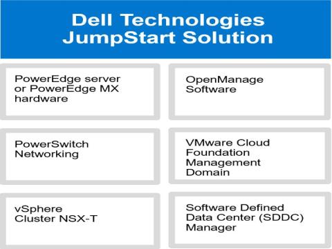
The Dell Technologies JumpStart Solution combines PowerEdge or PowerEdge MX hardware, OpenManage software, and Dell Technologies PowerSwitch networking with VMware Cloud Foundation into a fully-featured, easy-to-deploy Software-Defined Data Center (SDDC). A solution that provides the compute, storage, and networking resources to meet today’s business requirements and scalability to meet future requirements.

Introduction
This Solutions Guide provides instructions about configuring, deploying, and implementing the Dell Technologies JumpStart Solutions. This guide is designed to work with the Dell Technologies VMware Cloud Foundation for PowerEdge Deployment Guides. The deployment of a VMware Cloud Foundation Management Domain is the same as the previous guides with only minor changes. Any changes made from the original guides will be described here. For more information, see the Dell Technologies VMware Cloud Foundation for PowerEdge MX7000 and Dell Technologies VMware Cloud Foundation for PowerEdge Rack Deployment Guides are available at www.support.dell.com.
Audience and Scope
Before deploying this JumpStart Solution, ensure that you have the following:
- Knowledge about PowerEdge MX7000 or PowerEdge Rack Server products including the location of buttons, cables, and components in the hardware. For information about MX7000 systems, visit https://www.dell.com/support/home/enin/products/server_int/server_int_poweredge/server_modular_infrastructure?app=products.
- Functional knowledge about the components as described in the Dell Technologies product Owner’s Manuals and Service and Installation Guides of respective systems.
- Knowledge about VMware products, components, and the features of VMware Cloud Foundation.
- Best practices about managing data centers infrastructure components such as server, storage, networking, and environmental consideration—such as power and cooling.
- Complete knowledge of the network environment into which this JumpStart Solution will be deployed.
For more information about deploying a Cloud Foundation Management Domain, see the Dell Technologies VMware Cloud Foundation Deployment Guides available on www.support.dell.com. The scope of this Solutions Guide includes only the specific hardware and software components mentioned in this guide and excludes the existing infrastructure components. Dell Technologies does not take responsibility for any issues that may be caused to an existing infrastructure during deployment.
Dell Technologies JumpStart network architecture
The JumpStart Solution is built on simplified network architecture. In this design, the hosts are connected to a pair of ToR (Top of Rack) switches. While the rack server configuration is obvious, the MX configuration, using the pass-through Input Output Modules (IOMs) is the same but less obvious.
Using the pass-through IOM directly connects the A-fabric NIC port to the corresponding external port on the pass-through IOM. This is the same as the connectivity for the rack-based ToR except that the modular servers must pass through this additional layer of physical connection adapter.
The overall design is one where the connections from the servers to the ToR switches are trunked (not aggregated) with all the VLANs required. Routing is accomplished at a layer above the ToR switches. This connection diagram shows a simplified diagram of the network architecture.

Figure 1 JumpStart network connection architecture
Note that the ToR switches could be replaced with MX7000 modular switches and the R640 rack servers could be replaced with either R740 rack servers or MX740c modular compute sleds, as appropriate. The overall diagram is conceptionally appropriate for either rack or MX7000 modular deployments. The out-of-band management network has been omitted from this diagram to make the data paths easier to visualize.
Out-of-Band Management Network
Out-of-Band (OoB) management traffic for Management Modules (MX), Idriss (Rack), and switch management should be a simple flat network but there are no specific requirements for OoB management networking.
Dynamic Routing
In the example environment deployed here, Border Gateway Protocol (BGP) was used in the upper layer routing. NSX-T will be configured to exchange route information through BGP with the existing routers. While BGP is not a mandate, it does simplify the deployment by eliminating the necessity to add multiple static routes. Because the use of BGP is the recommended route, we will follow the BGP deployment path in this example.
IMPORTANT—Before deploying the JumpStart Solution, review the guidelines and best practices described in this section with your network team. Read the requirements and guidelines listed in the following sections:
- Network requirements for installing Cloud Foundation and SDDC Manager
- Additional Networks
- Network services
Network requirements for installing VM Cloud Foundation and SDDC Manager
Cloud Foundation and the SDDC Manager require a minimum number of networks for a basic installation. At least, the following four networks are required:
- Management network
- vSAN network
- vMotion network
- Host Overlay network
Jumbo frames or an MTU size of 9,000 is recommended on all VLANs. A minimum MTU value of 1,600 is required for the “Overlay” networks.

Management network
The management network is the network used to access different components of VM Cloud Foundation and it is the network on which the VM Cloud Foundation hosts are managed. This network does not require an MTU size larger than the minimum MTU but there is no issue if the network has an MTU larger than the Ethernet standard.
vSAN network
By default, VM Cloud Foundation uses vSAN storage. A vSAN will be created when VM Cloud Foundation is deployed. This network is used to share storage across the Cloud Foundation cluster. This network must:
- Support at least 10 Gbps data.
- Having jumbo MTU size (actual size based on other switches in the environment) is highly recommended.
vMotion network
vMotion is used to move VMs from one Cloud Foundation cluster host to another in case of:
- A failure
- Updating a host that may require a reboot or that may be offline for an extended period.
The vMotion network shares the same characteristics as the vSAN network. - At least 10 Gbps
- Jumbo MTU size (actual size based on other switches in the environment) is highly recommended.
Host Overlay network
The host Overlay network is used by NSX-T for control plane communication between the hosts of the Cloud Foundation cluster. The Overlay networks require an absolute minimum of 1,600 (again, an MTU of 9,000 is recommended).
Additional networks
In addition to the minimum required network types listed above, there are three additional networks required to complete your NSX-T networking. NSX-T provides virtual network services—routing, NAT, VPN, load balancing, and a firewall.
Uplink networks 1 and 2 for NSX-T data traffic
The uplink networks are used by NSX-T for data traffic into and out of the cluster. It is highly recommended that the uplink networks have an MTU of 9,000. Each of the two required NICs will use only one of the two Uplink networks. Each of these networks will be constrained to only one uplink.
These two uplink networks will be routed connections between the router and their corresponding IP interfaces on the Edge Nodes. To constrain the uplink traffic to only one physical link, each of the router members will have only an IP interface for one of the two uplink networks. The first router member will have an IP interface on VLAN 2711 (172.27.11.1/24). The second router member will have an IP interface on VLAN 2712 (172.27.12.1/24).
Network services
Figure 2 Layer 2 and Layer 3 Connectivity

IMPORTANT—If VLT (Virtual LAN Trunking) is implemented between the router members then both 2711 and 2712 VLANs must be created on both the router members. Inability to create the VLANs on each of the router members causes an imbalanced L2 VLT configuration and will cause the routing required for the Edge Cluster to fail.
Edge Overlay network
This network is used by the Edge Nodes in an NSX-T environment to enable the transport nodes to access the capabilities of the NSX-T Data Center.
Network services
The network services for PowerEdge MX7000 compatibility must be the same as the network services used for VMware Cloud Foundation deployment. The different network services are:
- Domain Name Service (DNS)
- Dynamic Host Control Protocol (DHCP)
- Network Time Service (NTP)
Hardware requirements for deploying the JumpStart Solution
The hardware components are the same as listed in the Dell Technologies VMware Cloud Foundation 4.0 for PowerEdge MX7000 and Dell Technologies VMware Cloud Foundation 4.0 for PowerEdge Rack Server Deployment Guides.
Deploy the JumpStart Solution
The deployment of JumpStart Solution has the following major tasks:
- Deploy VM Cloud Foundation Management Domain cluster
- Configure SDDC Manager to communicate with VMware software bundle repositories
- Configure access to online software bundles
- Deploy Proxy to enable access to VMware
- Get access to VMware software bundles
- Manage software bundles in VM Cloud Foundation
- Deploy an NSX-T Edge Cluster

Deploy VM Cloud Foundation Management Domain cluster
The Jump Start process starts with a standard Cloud Foundation deployment. One important difference is the option to “Deploy Application Virtual Networks”. In a Standard Cloud Foundation deployment, you are presented with the option to deploy and configure Application Virtual Networks (AVNs). Dell Technologies recommends that you do not deploy the AVNs as part of the Cloud Builder process. Instead, deploy the Edge Cluster to the Management Domain hosts through SDDC Manager after the Management Domain is deployed. Ensure to enable/disable by selecting (Yes/No) in the deployment parameter sheet that addresses the option to deploy these networks.
Configure SDDC Manager to communicate with the VMware software bundle repositories
Up to this point, the Cloud Foundation deployment has followed the procedure described in the current deployment guides. After the Management Domain is deployed, you can configure the Management Domain by doing the following:
- Configure SDDC Manager for access to the VMware online software bundles.
- Update Cloud Foundation, if necessary.
- Configure an NSX-T Edge Cluster.
Configure access to online software bundles
After deploying the Management Domain, the SDDC Manager must access and download software bundles from VMware. To enable access, ensure that SDDC Manager has network access to VMware.com and our VMware.com credentials that are registered to your licensed software.
Deploy Proxy to enable access to VMware
Because this management network is a private network, a proxy has been deployed to enable access out to vmware.com. If your management network has access to the internet, then no proxy is required. The proxy must meet the following requirements:
- It must be a transparent proxy
- It must not require user authentication
- It must be accessible from the SDDC Manager VM
After the proxy is created, configure the SDDC Manager to utilize the proxy. To enable this, start the connection to the VM by using SSH by doing the following:
- Start an SSH session using either the DNS name or IP address of the SDDC Manager VM.
- Log in as “vcf” and use the password that you set in the Cloud Builder parameter file.
- Run the su command to root using the password that you set in the Cloud Builder parameter file.
- Edit the /opt/vmware/vcf/lcm/lcm-app/conf/application-prod.properties file.
- Add the following three lines to the bottom of the application-prod.properties file:
lcm.depot.adapter.proxyEnabled=true
lcm.depot.adapter.proxyHost=<IP address of proxy server>
lcm.depot.adapter.proxyPort=<listening port configured on proxy server> - Save the file and restart the “LCM service” by running the command: systemctl restart lcm
- Wait for five minutes, and then Get access to VMware software bundles.
Get access to VMware software bundles
- On the SDDC Manager Graphical User Interface (GUI), in the left pane, under Administration, click Repository Settings.
Figure 3 Authenticate to get access to VMware software bundles - In the working pane, click Authenticate.
- Enter the email address and password to which your VMware products are associated.
- Click Authorize.
SDDC Manager now has access to the software bundles available on the VMware online repositories.

After these credentials are set, your Repository will begin to populate with available bundles. This population may take some time because the SDDC Manager, by default, is configured to obtain bundles every five hours.
Manage software bundles in VM Cloud Foundation
- To view the bundles that are now available for download, in the left pane, click Bundle Management.
A list of bundles and their availability status for downloading is displayed in the working pane: - Before you proceed, check if there are any VMware Cloud Foundation updates, download them, and then install them.

Figure 4 Available software bundles in SDDC Manager
Deploy an NSX-T Edge Cluster
An NSX-T Edge cluster consists of two edge nodes that will function as the transport nodes for NSX-T. SDDC Manager will be used to deploy the Edge Node Cluster. You must know information about your BGP−routed environment, VLANs, and subnets that have been physically deployed (to the switches and routers) to create the cluster.
Fully Collapsed vSphere Cluster NSX-T
The prerequisites for this type of deployment (as per VMware documentation) are:
- All the hosts must be part of a vSphere cluster.
- Each host has two physical NICs enabled.
- Register all hosts to a vCenter Server.
- Verify on the vCenter Server that shared storage is available to be used by the hosts.
- The host Tunnel Endpoint (TEP) IP and NSX Edge TEP IP must be indifferent VLAN segments. Any north-south traffic coming from host workloads is encapsulated in the GENEVE packet format, and sent to an NSX Edge node with:
• Source IP=host TEP
• Destination IP=NSX Edge TEP
Because these TEPs must belong to different VLANs or subnets, traffic must be routed through Top-of rack (TOR) switches. The reason to configure separate VLANs for the host TEP and NSX Edge TEP is that aTEP can receive traffic from or send traffic to only on physical network adapter but not from an internal port group.
Deploy an Edge Cluster
Edge Cluster creation requires in-depth knowledge of the upstream network to which this solution is connected. Before deploying an Edge Cluster, review this section with your network teams.
To install an Edge Node cluster, navigate to the SDDC Manager Graphical User Interface (GUI). On the SDDC Manager Dashboard page:
- In the left pane, expand Inventory, and then click Workload Domains.
- Click the management domain.
Information about the selected management domain is displayed. - Expand Actions.
- Click Add Edge Cluster.
This will begin the process to create the Edge Cluster. The process will deploy the cluster as well as deploy and configure the edge nodes, transport nodes, and all the connections up to the routed environment. If you do not use a Border Gateway Protocol (BGP) environment, you will need to create static routes for all the subnets as the process continues.
To create an Edge Cluster you must have complete information about your BGP environment and DNS entries. Therefore, it is recommended that you seek assistance from your network administrators in this task.


Add an Edge Cluster
- Before you start adding an Edge Cluster, ensure that you select appropriate checkboxes to indicate that you have fulfilled the prerequisites and then click BEGIN.
- Enter a cluster name.
- Enter the MTU value. The recommended value is 9,000.
- Specify the Autonomous System Number (ASN) of the autonomous system that you want to create (must be configured as a remote autonomous system on your upstream Border Gateway Protocol (BGP) router).
- Name your tier 0 and tier 1 gateways.
- Set the profile type to Default.
- Enter the passwords for the different users.
- Click Next.
- Select Workload Management. All fields are automatically populated.
- Click Next.
- In the Edge Node Details dialog box, enter the following data:
a. Enter the Edge Node FQDN (enter a corresponding DNS entry).
b. Enter the Management IP address and default gateway numbers.
c. Enter the Edge TEP IP address, gateway, and VLAN numbers.
• Each edge node will have two IP addresses on the Edge Overlay network.
• These IP addresses must not conflict with the second Edge Node.
• In this example, the VLAN is 2713 and the subnet is 172.27.13.0/24.
d. Select the name of the cluster that you named earlier.
e. Select L2 Uniform as the cluster type.
f. Create the required uplinks. Each uplink gets a different VLAN. In this example, they are 2711 and 2712.
g. Specify the IP address for the Edge Node interface.
h. Specify the IP address on the upstream router for this VLAN.
i. Specify the remote autonomous system (of the upstream router).
j. Enter BGP password (set on the upstream router to authenticate the edge node)
k. Add a second Edge Node by clicking ADD MORE EDGE NODES. - Repeat each of these steps for the second uplink, and then click NEXT.
- Review the summary. Ensure that your BGP settings match those of your upstream router and ensure that all the specified FQDNs are properly configured on DNS.
- When you are satisfied with the summary information, go to the validation phase by clicking NEXT. The validation process is immediately started, which takes around 10 minutes. If validation fails, check the error message and determine the cause of the issue(s). After successfully validating, click FINISH to deploy the edge cluster.


JumpStart Solution is deployed and ready
After successfully creating the Edge Node Cluster, you have the following installed and configured—all running on a vSAN:
- A fully functional VCF Consolidated Architecture cluster.
- SDDC manager
- VCenter
- NSX Manager
- Associated NSX-T controllers and edge nodes have been installed and configured
- Access to the VMware software bundles is tested and functional.
- The Cloud Foundation stack is updated to the latest available version.
- An NSX-T Edge Node Cluster has been deployed and is ready for any tasks that might be required.
Licensed software bundles can be deployed to this cluster via SDDC Manager. Resource groups can be created and virtual workloads can now be deployed.
The deployed JumpStart Solution represents the fastest path into the realm of the private cloud. The deployed solution contains an entire suite of tools designed to provide the ability to manage both the physical and virtual infrastructure running on best-in-class Dell EMC servers and networking. This combination of VMware Cloud Foundation and Dell EMC PowerEdge servers provides a powerful, fault-tolerant, and easy to manage hyper-converged infrastructure.
This private cloud platform can be enhanced by the deployment of additional software bundles to provide:
- Lifecycle management
- Operations and performance monitoring
- Workload deployment automation
- Modern application infrastructure (Tanzu, Kubernetes)
- Network micro-segmentation
While the initial deployment is only four hosts, additional Cloud Foundation workload domains can be deployed later to scale out this private cloud infrastructure. Through network virtualization, the solution can be connected to public and private cloud providers to transform this private cloud solution into a hybrid cloud solution.